Range Rover Evoque: Central Junction Box (CJB)
Removal
CAUTIONS:
If a new component is to be installed, the Land Rover approved diagnostic equipment must be connected prior to removal, the data must then be downloaded from it and the keys (remote control handsets) set into default mode. Failure to follow this instruction will result in permanent damage to the keys.
A maximum of 4 remote transmitters can be programmed to the anti-theft alarm and double locking module.
Programming for all remote transmitters must be carried out at the same time.
NOTES: Removal steps in this procedure may contain installation details.
Make sure that all keys (remote control handsets) are present when performing this procedure.
1. If a new Central Junction Box (CJB) is to be installed, use Land Rover approved equipment to upload the stored data.
2. Refer to: Specifications (414-01 Battery, Mounting and Cables, Specifications).
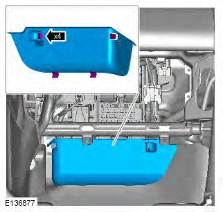
3. Refer to: Glove Compartment (501-12 Instrument Panel and Console, Removal and Installation).
4.
5.
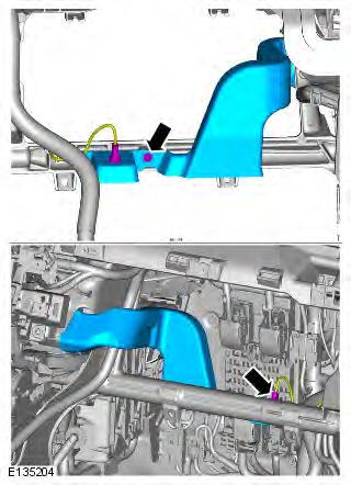
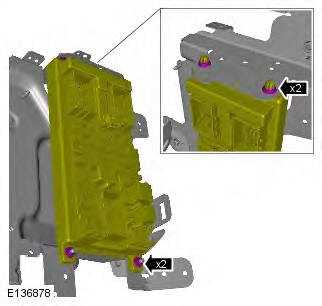
6.
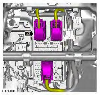
7.
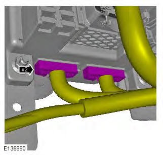
8. Torque: 8 Nm
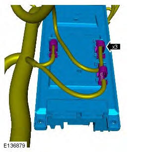
9.
Installation
1. To install, reverse the removal procedure.
READ NEXT:
 Battery Junction Box (BJB) TD4 2.2L
Diesel
Battery Junction Box (BJB) TD4 2.2L
Diesel
Removal
NOTES:
Removal steps in this procedure may contain installation details.
Some variation in the illustrations may occur, but the essential information is
always correct.
All vehicles
1. Refer
Battery Junction Box (BJB) GTDi 2.0L
Removal
NOTES:
Removal steps in this procedure may contain installation details.
Some variation in the illustrations may occur, but the essential information is
always correct.
All vehicles
1. Refer
Communications Network - Overview, System
Operation and Component Description
Overview
A number of different types of communication networks are incorporated into
the vehicle wiring harnesses for the
transmission of commands and information between control modules. The
config
SEE MORE:
Battery Junction Box (BJB) TD4 2.2L
Diesel
Removal
NOTES:
Removal steps in this procedure may contain installation details.
Some variation in the illustrations may occur, but the essential information is
always correct.
All vehicles
1. Refer to: Specifications (414-01 Battery, Mounting and Cables,
Specifications).
2. Refer to: Central Junc
Battery Junction Box (BJB) GTDi 2.0L
Removal
NOTES:
Removal steps in this procedure may contain installation details.
Some variation in the illustrations may occur, but the essential information is
always correct.
All vehicles
1. Refer to: Specifications (414-01 Battery, Mounting and Cables,
Specifications).
2. Refer to: Central Junc
