Range Rover Evoque: Communications Network - Overview, System Operation and Component Description
Overview
A number of different types of communication networks are incorporated into the vehicle wiring harnesses for the transmission of commands and information between control modules. The configuration installed on a particular vehicle depends on the model and equipment level.
The communication networks available on the vehicle are:
- LIN (local interconnect network) bus
- Medium speed CAN (controller area network) bus
- High speed CAN bus
- Media Orientated System Transport (MOST) ring
System Operation and Component Description
Control Diagram
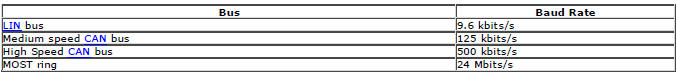
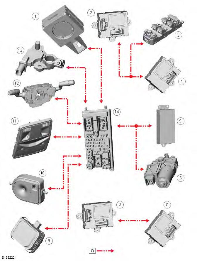
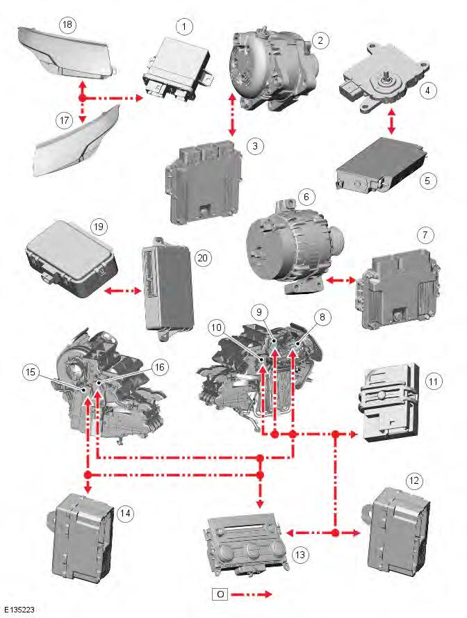
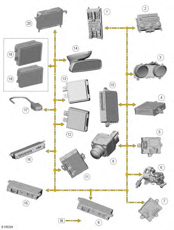
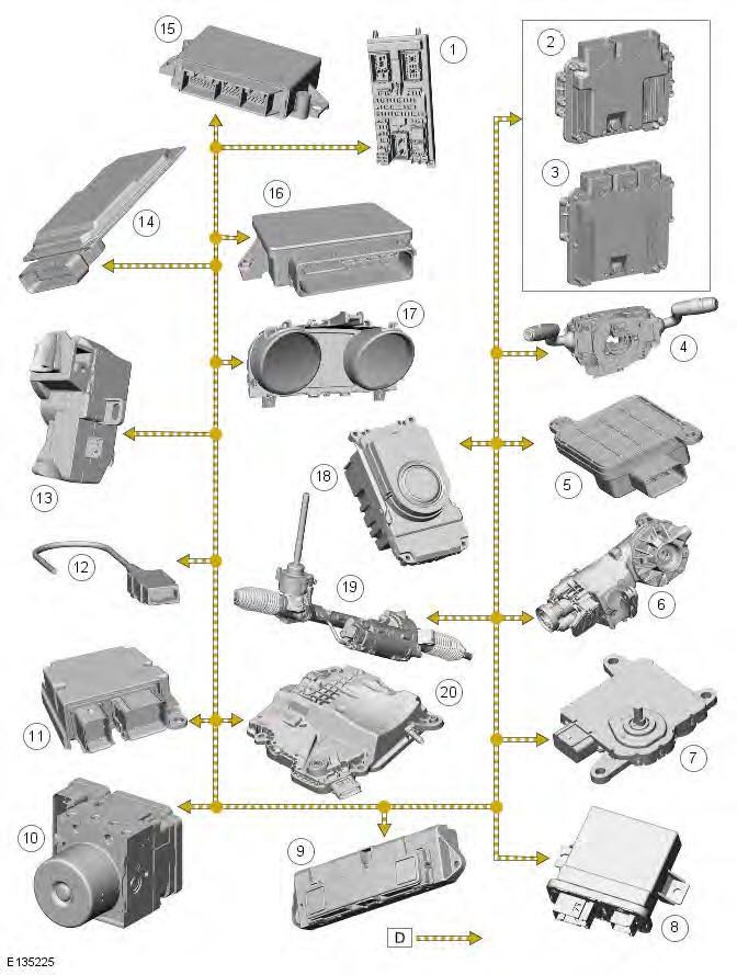
NOTE: O = LIN (local interconnect network) bus; N = Medium speed CAN (controller area network) bus; D = High speed CAN bus; P = MOST
CONTROL DIAGRAM - LIN BUS (SHEET 1 OF 2)
- Immobilizer Antenna Unit (IAU)
- Driver door module
- Driver door switch pack
- Rear door module (driver side)
- Voltage quality module
- Roof blind motor
- Rear door module (passenger side)
- Passenger door module
- Rain sensor
- Battery backed sounder (if fitted)
- Front overhead console
- Clockspring
- Battery Monitoring System (BMS) module
- CJB (central junction box)
CONTROL DIAGRAM - LIN BUS (SHEET 2 OF 2)
- Headlamp control module
- Generator (DW12c)
- ECM (engine control module) (DW12c)
- TCM (transmission control module)
- Auxiliary battery module
- Generator (GTDi)
- ECM (GTDi)
- Fresh/recirculated mode motor
- Screen air distribution motor
- RH (right-hand) air temperature mode motor
- Cabin humidity sensor
- Passenger heated seat module
- Integrated Control Panel (ICP)
- Driver heated seat module
- LH (left-hand) air temperature mode motor
- Face/feet mode air distribution motor
- LH headlamp
- RH headlamp
- Radio Frequency (RF) receiver
- Keyless Vehicle Module (KVM)
CONTROL DIAGRAM - MEDIUM SPEED CAN BUS
- CJB
- Integrated Control Panel (ICP)
- Instrument cluster
- Navigation system module (Asia)
- Driver door module
- Fuel Fired Booster Heater (FFBH)
- Passenger door module
- Passenger seat memory module
- Rear view camera
- Keyless Vehicle Module (KVM)
- Liftgate module
- RH blind spot monitoring module
- LH blind spot monitoring module
- Interior mirror
- Driver seat memory module
- Proximity camera control module
- Diagnostic socket
- Touch Screen Display (TSD) - single view
- Touch Screen Display (TSD) - dual view
- Multi-function display
CONTROL DIAGRAM - HIGH SPEED CAN BUS
- CJB
- ECM (GTDi)
- ECM (DW12c)
- Clockspring
- Occupancy sensor module
- Differential electronic module
- TCM
- Headlamp control module
- Terrain optimization switch
- ABS (anti-lock brake system) module
- RCM (restraints control module)
- Diagnostic socket
- Electric steering column lock
- Continuously variable damping module
- Park distance control module
- Electric park brake module
- Instrument cluster
- Electronic Transmission Selector (ETS)
- Electrical power assisted steering rack
- Gear shift module
CONTROL DIAGRAM - MOST
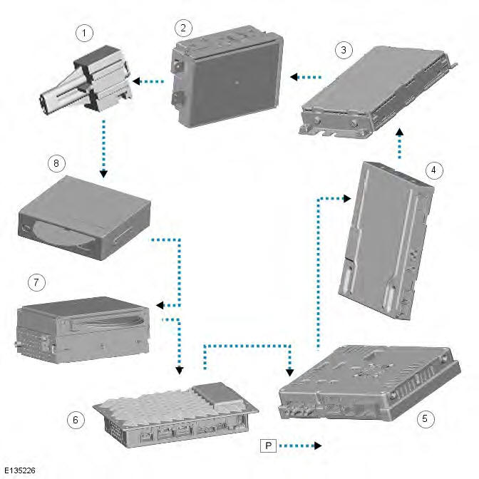
- Diagnostic socket
- Touch Screen Display (TSD)
- Satellite Digital Audio Radio Service (SDARS) module (NAS Only) or Digital Audio Broadcasting (DAB) module
- Rear Seat Entertainment (RSE) module
- TV Module
- Audio power amplifier
- Integrated Audio Module (IAM)
- Navigation control module (Japan only)
System Operation
Principles of operation
Refer to: Communications Network (418-00 Module Communications Network, Description and Operation). and to Component Description below.
Component Description
LOCAL INTERCONNECT NETWORK BUS
The LIN bus is a low speed broadcast network that employs master and slave components. The master component transmits a message along a single wire to the slave components identifying which slave is to respond. The message has a header (slave identifier) and an empty data field. The identified slave component fills the data field with the relevant information and returns a message to the master component along the same wire.
CONTROLLER AREA NETWORK BUS
The CAN bus is a high speed broadcast network where control modules automatically transmit information every few microseconds. Information is broadcast down a pair of twisted wires, known as 'CAN high' and 'CAN low'. Information is transmitted on the CAN bus as a voltage difference between the 2 wires.
Two CAN bus networks are used on the vehicle; medium speed and high speed, with the CJB acting as a gateway between the 2 networks. The table below shows the wire colors used on both networks.

MEDIA ORIENTATED SYSTEM TRANSPORT (MOST) RING
The Media Orientated System Transport (MOST) ring uses fiber optic cables to transport data and audio signals around the information and entertainment system. The fiber optic cables are arranged in a ring, with each unit on the ring having a 'MOST in' and 'MOST out' connection.
The MOST ring is a synchronous network. A timing master supplies the clock and all other components on the ring synchronize their operation to this clock. The timing master for the MOST ring is the integrated control module.
When handling MOST fiber optic cables the following precautions should be observed:
- After disconnection of any cables carefully install appropriate dust caps to protect the mating faces of the connectors from damage and contamination.
- Avoid introducing bends of less than 25 mm (0.98 inches) radius or kinks into the fiber optic cable during service or repair. Tight bends or kinks could impair operation, cause immediate system failure, or future system failure.
- Avoid excessive force, strain or stress on the fibers or connectors especially permanent stress after reinstallation.
Ring Break Diagnostics
Incorporated into the CJB is a Ring Break Diagnostics (RBD) link. The RBD link houses a copper link which when removed initiates the ring break diagnostics mode. The ring break diagnostics mode allows the technician to locate an optical fiber break in the MOST ring. To initiate the ring break diagnostics mode, carry out the following process:
- Connect the Land Rover approved diagnostic system.
- Ensure the vehicle is in power mode 4 or greater.
- Remove the RBD link for the length of time specified by the Land Rover approved diagnostic system.
- Replace the RBD link.
After approximately 30 seconds a DTC (diagnostic trouble code) will be logged in the Integrated Control Module, identifying the location of the fault. The DTC can be read and interrogated using the Land Rover approved diagnostic system.
READ NEXT:
 Communications Network - Diagnosis and Testing
Principles of Operation
For a detailed description of the Communications Network, refer to the
relevant Description and Operation sections in the
workshop manual.
Inspection and Verification
CAUTIONS
Wiring Harness - Description and Operation
Introduction
CAUTION: Do not use any other heat shrink sleeve other than the approved
glue lined heat shrink sleeve mentioned
in the repair procedure.
The purpose of this document is to promote quic
SEE MORE:
Important information
The information contained in this handbook covers all vehicle derivatives and
optional equipment,
some of which may not be fitted to your vehicle. Due to printing cycles, this
handbook may include
descriptions of options before they become generally available.
The vehicle options, hardware an
Symbols used in this handbook
Safety warnings indicate either a procedure which must be followed
precisely, or
information that should be considered with great care, in order to avoid the
possibility
of personal injury.
Cautions indicate either a procedure which must be followed precisely, or
information that
should
