Range Rover Evoque: Wiring Harness - Description and Operation
Introduction
CAUTION: Do not use any other heat shrink sleeve other than the approved glue lined heat shrink sleeve mentioned in the repair procedure.
The purpose of this document is to promote quick and efficient minor repair to harness connectors or cables using approved methods and the wiring harness repair kit. Repairs may only be made to cables and connectors which have been mechanically, not electrically damaged. It also applies where the whole extent of the damage can be clearly identified and rectified.
Care and neatness are essential requirements in making a perfect repair.
Caution:
At the time of this first issue of the Harness Repair Guide, do not approve repairs to any of the following circuits:
- Any media orientated system transport network harnesses.
- Supplement restraint system (SRS) firing circuits (Air bags).
- Link lead assembles, which are unique to safety critical circuits such as anti-lock brake system (ABS) and thermocouple circuits. An example of this is the ABS wheel speed sensors with moulded connectors.
- 4. Screened cables, leads and wiring harness(s).
If any harness(s) with defective electrical connector terminals or wires from the above circuits are a concern, new components must be installed.
Repair Kit
CAUTION: Where the repair procedure indicates that a glue lined heat shrink sleeve should be applied, apply sufficient heat to the glue lined heat shrink to melt the glue in order to provide a water tight seal. Do not over heat the glue lined heat shrink sleeve so that the wiring harness insulation becomes damaged.
The wiring harness repair kit has been produced which comprises:
- Pre-terminated wiring harness(s) of different sizes and types
- Three sizes of butt splice connectors
- A selection of colored cable identification sleeves
- Two sizes of glue lined heat shrink sleeves
- Crimping pliers
- A wire cutter and insulation stripper
- An electrical connector terminal extraction handle and tips
A suitable heat source, for shrinking heat shrink sleeves will be required.
The pre-insulated diamond grip range of electrical connector terminals and in-line, butt splice connectors contained within the wiring harness repair kit are the only acceptable product for the repairs of wiring harnesses. The butt connectors not only grip the wire but also the insulation, making a very secure joint.
If an electrical connector terminal is not included in the wiring harness repair kit then approval for the repair is NOT given and in these circumstances a new wiring harness must be installed.
Pre-Terminated Wiring Harness(s) and Butt Splice Connectors
All pre-terminated wiring harness(s) and butt splice connectors in the wiring harness repair kit are contained in bags which can be resealed after use. Each bag is marked with the part number of the items stored within the bag. Each storage compartment in the wiring harness repair kit is identified with the corresponding part number. Make sure that pre-terminated wiring harness(s) and connectors are not mixed up it is advisable to only open one bag at a time and to reseal the bag securely before opening another bag. Also, replace the bag in its mating part number compartment within the case.
The pre-terminated wiring harness(s) are supplied with the insulation in one of three colors, red, blue or yellow. The colors do not apply to any particular circuit but to the harness wire size. See the Relationship Table in the Repair Method section.
Butt splice connectors are also supplied with red, blue or yellow coverings, which must be matched to the pre-terminated wiring harness insulation color.
Pre-Terminated Wiring Harness(s)
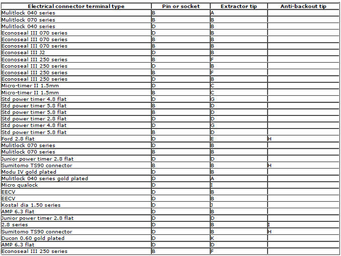
The illustration shows:
- The pre-terminated wiring harness(s) which are included in the wiring harness repair kit
- The part number of the pre-terminated wiring harness
- The letter showing the extractor tip which must be used to remove this type of electrical connector terminal
- Those electrical connector terminals which are gold
Some of the pre-terminated wiring harness(s) have seals installed to the insulation for sealed connector applications. It is essential for prevention of moisture ingress that a sealed pre-terminated wiring harness must be used where a sealed terminal was removed.
CAUTION: Where the repair procedure indicates that a glue lined heat shrink sleeve should be applied, apply sufficient heat to the glue lined heat shrink to melt the glue in order to provide a water tight seal. Do not over heat the glue lined heat shrink sleeve so that the wiring harness insulation becomes damaged.
Two sizes of heat shrink sleeving are supplied in the wiring harness repair kit. Each heat shrink sleeve contains a sealant glue. These must be used when connecting wiring harness(s) or electrical connector terminal(s) at all times. The smaller diameter heat shrink sleeve is to be used with the red and blue butt splice connectors and the larger diameter sleeve with the yellow butt splice connectors.
For ease and speed, some of the pre-terminated wiring harness(s) may already have the insulation partly stripped at the splice end. If the repair requires insulation to be stripped from the cable, refer to the Relationship Table for the correct length of insulation to be stripped.
The Pre-Terminated Wiring Harness(s) illustration shows the electrical connector terminal type, the part number of the pre-terminated wiring harness and the letter of the extractor tip which must be used to extract the electrical connector terminal from the connector housing. Additionally, those electrical connector terminal(s) which are gold are identified, all others are therefore, tinned and not gold.
Wiring Harness Cable Identification Sleeves A selection of colored sleeves are contained in the wiring harness repair kit for maintaining the wiring harness cable identification on the pre-terminated wiring harness. Place the correct colored sleeve(s) over the pre-terminated wiring harness insulation as near to the electrical connector as possible with the main wiring harness cable color nearest to the electrical connector.
For example, if the original wiring harness cable color is pink with a black trace put the pink wiring harness cable identification sleeve on the pre-terminated wiring harness first followed by a black sleeve, and slide both along the wiring harness cable to the electrical connector terminal.
Extraction Handle and Tips
The extraction handle, in conjunction with the correct tip, is used to remove a terminal from an electrical connector. Each tip contained in the wiring harness repair kit is marked with an identification letter, A to K inclusive. Each tip has been specially designed to extract a particular type of electrical connector terminal. The use of any other tool is not recommended and is liable to cause damage to the electrical connector. The tip is fastened to the handle by a screw which holds the tip firmly yet allows it to be easily replaced.
Extraction Handle and Tips
Insulation Stripper
The moving jaw has an adjuster wheel which has a series of holes in it. Turning the wheel and placing the cable in the matching size hole will automatically adjust the jaw to the correct pressure. Note that some wiring harness(s) may have a harder insulation and slight adjustment of the wheel may be needed to make a clean strip but exercise care not to damage the wire.
Insulation Stripper
By pressing the outer edges of the wiring harness cable length stop together the adjuster can be slid up or down the jaw.
This decreases or increases the length by which the wiring harness cable insulation will be stripped from the pre-terminated wiring harness or wiring harness wire. The adjuster has a position indicator to align with a graduated scale and this sets the correct length in millimetres, of insulation to be stripped. The amount of insulation to be stripped is shown in the Relationship Table.
The illustration shows the insulation stripper tool and a wiring harness correctly gripped in the jaws. A wire cutter is provided on the outer side of the fixed jaw.
Cable Correctly Gripped in Stripper Blades
Crimping Pliers
Crimping Pliers
The crimping pliers have a moving jaw and a stationary jaw, with three different sized crimping enclosures. Each of the enclosures is identified by a red, blue or yellow coloured dot which corresponds to the three colours of the pre-terminated wiring harness(s) and butt splice connector colors.
List of Parts
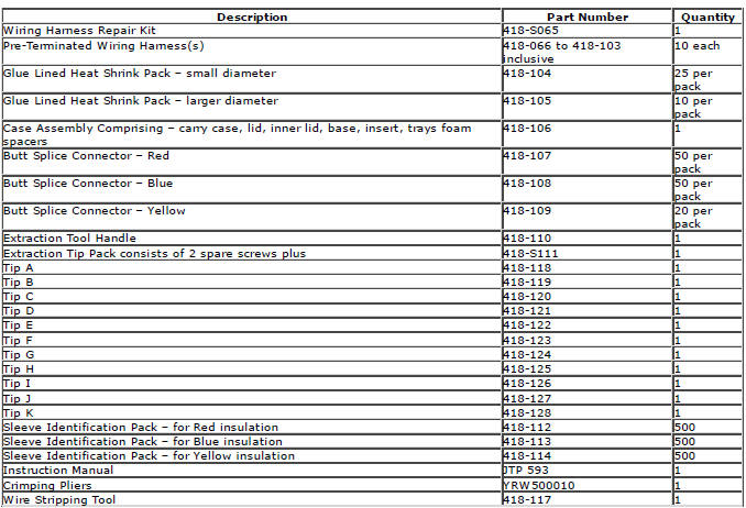
Items can be ordered from:
SPX United Kingdom Limited
Ironstone Way
Brixworth
Northants
NN6 9UD
United Kingdom
Telephone: +44 (0) 1327 704461
Fax: +44 (0) 1327 706632
Repair Methods
CAUTION: Several different types and sizes of terminal may be found in a single electrical connector housing.
It is necessary to identify:
- The conductor (wire) size of the affected wiring harness
- The electrical connector range from which the damaged wiring harness is to be removed
- The terminal type
Use of the approved diagnostic tool will greatly assist in the quick identification of electrical connectors and faulty pin terminal(s).
Reference can also be made to the vehicle Electrical Guides, held by Dealers, to identify wiring harness(s) and electrical connector(s).
By using the Relationship Table, the wiring harness conductor (wire) size can be related to a suitable pre-terminated wiring harness by the color of the insulation. Also, the correct length of insulation to be stripped from the wiring harness lead is identified.
Relationship Table

Electrical Connector Terminal Extraction
It must be noted that some electrical connector(s) have anti-backout devices which prevent the terminals from being removed from the electrical connector. Some examples of these are shown in following illustrations. The anti-backout device must be released before attempting to remove the terminal from the electrical connector. Some anti-backout devices require a special tip to release the device and these have been included in the kit. Most can be released by carefully using a suitable small screwdriver.
Various types of electrical connector have seals installed internally or externally to prevent moisture ingress. These normally do not have to be removed but make sure that they are installed when the electrical connectors are connected.
The illustrations show examples of each tip used on different types of electrical connector(s). There are a large number of different types of electrical connector used on vehicles therefore only one example using each tip is shown. Technicians experience and judgement will dictate which type of tip should be used for those electrical connector(s) which are not shown. Care should be exercised to avoid further damage when removing the terminals from the electrical connector.
NOTE: Examples of the extraction tips and anti-backout tips.
NOTE: The chart shows the electrical connector types, terminal pins/sockets, extractor tip and anti-backout tip.

Repair Procedure
CAUTIONS:
Do not use crimping pliers, insulation strippers, butt splice connectors, heat shrink sleeves or pre-terminated wiring harness(s) that are not supplied with the Jaguar wiring harness repair kit. Each part has been designed to be used only with the other parts in this wiring harness repair kit.
Where the repair procedure indicates that a glue lined heat shrink sleeve should be applied, apply sufficient heat to the glue lined heat shrink to melt the glue in order to provide a water tight seal. Do not over heat the glue lined heat shrink sleeve so that the wiring harness insulation becomes damaged.
It is not correct to make more than five repair joints on the wiring harness to any electrical connector and if more damage is found at the same electrical connector then a new wiring harness must be installed.
- Remove the faulty terminal from the electrical connector using the extractor tool and correct tip. Make sure that any anti-backout device is released before trying to remove the terminal.
- CAUTION: : A number of electrical connector terminals are gold plated or gold flashed. When defective, they must be installed with a gold pre-terminated wiring harness(s) from the wiring harness repair kit. It is not always easy to identify the female as gold but the male pins are visually easier, therefore always check both male and female terminals to identify those which are gold. Under no circumstances are gold and tin terminals to be mixed as this will lead to early failure of the electrical contact.
NOTE: Never use a harness lead with a smaller diameter than the original harness lead.
Select the correct size and type of pre-terminated wiring harness and butt splice connector from the wiring harness repair kit.
- Using the wire cutter on the stripping tool, cut the pre-terminated wiring harness and the harness cable to the required length.
- NOTE: See illustration: Stripping Insulation
From the Relationship Table, find the correct length of insulation to be stripped from the pre-terminated wiring harness and set the adjustable cable length stop to the correct length. Place the pre-terminated wiring harness in the wire stripper and remove the insulation.
- Put the cable identification sleeve(s) on to the wiring harness with the main cable colour nearest to the terminal.
- During this next step do not over tighten. Place the selected butt
splice connector in the crimping tool, matching the aperture and the butt
connector colours. Make sure that the window indentation in the butt
connector is resting
over the guide bar on the lower jaw. Partially close the grip until the butt
connector is securely held in the aperture.
This will give support to the butt connector while the pre-terminated wiring harness is inserted into it.
- NOTE: See illustration: Splice Correctly Located
Insert the pre-terminated wiring harness into the butt connector and make sure that the wire is against the wire stop. Close the grip firmly, crimping the lead to the butt connector. When the handles have been completely closed the butt connector will be freed from the tool as the handles are released. If the handles have not been completely closed then the jaws will hold the butt connector and it cannot be removed from the tool until the crimp is fully made by closing the handles completely.
- Make sure that the harness cable has been squarely cut and the correct length of insulation removed. If more than one splice is needed the butt connectors must be not be crimped to the wiring harness at the same distance from the connector. The splices must be staggered to prevent a bulk of splices in the same area of the wiring harness.
- It is preferable to cover the butt splice joint with heat shrink sleeve. This is desirable not essential, except where the electrical connector is a sealed electrical connector. Use the smaller diameter sleeve for red and blue pre-terminated wiring harness(s) and the large diameter sleeve for the yellow pre-terminated wiring harness(s). It is advisable to place the heat shrink over the completed joint but in some instances the sleeve will not pass over the terminal. Check, and if required, place the correct size sleeve onto the harness cable or pre-terminated wiring harness before crimping the butt splice to the wiring harness.
- Place the harness cable into the butt splice with the splice window over the guide bar. Make sure that the cable harness wire is against the stop in the butt splice, crimp the butt splice connector to the wiring harness.
- Gently pull the harness cables each side of the butt splice to make sure that a secure joint has been made.
WARNING: Do not use a naked flame in areas where fuel or oil have been spilt. Clean the area of residual oil and fuel and wait until the fuel spill has fully evaporated.
CAUTIONS: When using a heat source make sure that it is localised and causes no damage to surrounding materials.
Where the repair procedure indicates that a glue lined heat shrink sleeve should be applied, apply sufficient heat to the glue lined heat shrink to melt the glue in order to provide a water tight seal. Do not over heat the glue lined heat shrink sleeve so that the wiring harness insulation becomes damaged.
Using a suitable heat source, shrink the sleeve over the butt splice.
- If further pre-terminated wiring harness(s) are to be installed to the same electrical connector, make sure that the lead is cut at a different length to the previous joint. This makes sure that the splices will, where possible, be staggered on the wiring harness and prevent a bulk of splices in one area.
- When all of the splices have been made, fit the terminal(s) to the electrical connector, taking care that the terminals are correctly orientated.
- Install the wiring harness cover and secure with adhesive electrical tape. Do not cover the wiring harness right to the electrical connector as the terminals must have a little movement and not be firmly bound to the electrical connector or wiring harness. Make sure that the cable identification sleeve(s) are showing at the wiring harness electrical connector.
Stripping Insulation
Splice Correctly Located
Wiring Harnesses
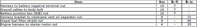
Torque Specifications
READ NEXT:
 Engine Wiring Harness TD4 2.2L Diesel, Vehicles With:
AWF21 6-Speed Automatic Transmission
Engine Wiring Harness TD4 2.2L Diesel, Vehicles With:
AWF21 6-Speed Automatic Transmission
Removal
CAUTIONS:
Make sure that the wiring harness is not twisted or damaged on removal. Failure
to follow this instruction may result
in damage to the vehicle.
Take extra care not to damage the wi
Engine Wiring Harness GTDi 2.0L Petrol
Removal
CAUTIONS:
Make sure that the wiring harness is not twisted or damaged on removal. Failure
to follow this instruction may result
in damage to the vehicle.
Take extra care not to damage the wi
Engine Wiring Harness TD4 2.2L Diesel, Vehicles With:
M66 6-Speed Manual Transmission AWD/M66 6-Speed Manual
Transmission FWD
Removal
CAUTIONS:
Make sure that the wiring harness is not twisted or damaged on removal. Failure
to follow this instruction may result
in damage to the vehicle.
Take extra care not to damage the wi
SEE MORE:
Important information
The information contained in this handbook covers all vehicle derivatives and
optional equipment,
some of which may not be fitted to your vehicle. Due to printing cycles, this
handbook may include
descriptions of options before they become generally available.
The vehicle options, hardware an
Symbols used in this handbook
Safety warnings indicate either a procedure which must be followed
precisely, or
information that should be considered with great care, in order to avoid the
possibility
of personal injury.
Cautions indicate either a procedure which must be followed precisely, or
information that
should
