Range Rover Evoque: Communications Network - Diagnosis and Testing
Principles of Operation
For a detailed description of the Communications Network, refer to the relevant Description and Operation sections in the workshop manual.
Inspection and Verification
CAUTIONS:
Diagnosis by substitution from a donor vehicle is NOT acceptable. Substitution of control modules does not guarantee confirmation of a fault, and may also cause additional faults in the vehicle being tested and/or the donor vehicle.
Electronic modules are sensitive to static electrical charges. If exposed to these charges, damage may result.
1. Verify the customer concern
2. Visually inspect for obvious signs of damage and system integrity
Visual Inspection
- Fuses (refer to electrical guide)
- Wiring harness
- Correct engagement of electrical connectors
- Loose or corroded connections
- Routing of fibre optic harnesses
- Correct engagement of optical connectors
- Correct placement of optical connectors (ring order)
- Correct assembly of optical connectors (backout, etc)
- Damage to fibre (chafing, abrasion, kinking, cuts, etc)
3. If an obvious cause for an observed or reported concern is found, correct the cause (if possible) before proceeding to the next step
4. If the cause is not visually evident, check for Diagnostic Trouble Codes (DTCs) and refer to the DTC Index
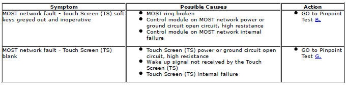
Symptom Chart
Controller Area Network (CAN)
Control Module Connections to the CAN Harness
Control modules are connected to the CAN harness either in a 'loop' or 'spur' configuration. In the 'loop' type configuration the CAN harness loops into the module (via two connector pins) and then loops out of the module (via another two connector pins). In the 'spur' type configuration, a harness spur is spliced into the main 'backbone' of the CAN harness and the module is connected to the harness spur via two connector pins.
CAN Harness Architecture
For a detailed description of the CAN Networks and architecture, refer to the relevant Description and Operation section in the Workshop Manual.
CAN Network Integrity Tests
If a control module is suspected of non-communication, the Network Integrity test application available on the manufacturer approved diagnostic system can be used to confirm if communication is possible between the control modules on the vehicle and the manufacturer approved diagnostic system (via the J1962 diagnostic connector ). The results from the test can be used to determine if either a single module or multiple modules are failing to communicate.
CAN Terminating Modules
If the Network Integrity test indicates that one or more module on one of the CAN networks (HS or MS) are failing to communicate, there are several checks that can be made. The first step is to identify if both of the CAN terminating modules on each individual CAN Bus are communicating. If both CAN terminating modules for each individual CAN Bus are communicating (identified via the Network Integrity test), then it can be confirmed that the main 'backbone' of the CAN harness is complete. The main 'backbone' of the CAN harness consists of all the modules connected to the CAN harness via a 'loop' configuration and also includes the two terminating modules.
Communication with both CAN terminating modules via the Network Integrity test confirms the physical integrity of the main 'backbone' of the CAN harness (and the harness spur to the J1962 diagnostic connector). This means that there is no requirement to check the resistance of the CAN Network. This is because the standard check for 60 ohms across the CAN High and CAN Low lines will not provide any additional information regarding the physical condition of the CAN harness, beyond what has already been determined from the Network Integrity test.
Non-Communication of a Terminating Module
If a Network Integrity test reveals a terminating module is failing to communicate it can indicate a break in the main 'backbone' of the CAN harness. The first checks should always be to confirm the power and ground supplies to the non-communicating module are correct. Providing these are correct, the resistance between the CAN High and CAN Low lines at the J1962 connector can be checked to determine the integrity of the main 'backbone' of the CAN harness. After disconnecting the battery a reading of 120 ohms would indicate an open circuit in the main 'backbone' of the CAN harness.
Alternatively, a reading of 60 ohms would indicate that there is no open circuit fault with the main 'backbone' of the CAN harness.
It is worth noting that even if one of the terminating modules is disconnected from the CAN harness, communications between the modules still connected may still be possible. Therefore communication between the manufacturer approved diagnostic system and the connected modules may also be possible.
Locating CAN Harness Open Circuits
In the case where multiple modules, including a terminating module, are failing to communicate, having first confirmed the power and ground supplies are correct, the approximate location of the open circuit can be identified from analysis of the Network Integrity test results and reference to the relevant CAN network circuit diagrams. For example, if an open circuit existed in a certain position on the CAN harness, any module positioned on the Network between the J1962 connector and the open circuit should return a response during the Network Integrity test. No responses would be returned from any modules past the open circuit fault in the Network.
CAN Harness 'Spur' Type Configuration Circuits
If, after the initial checks (Network Integrity test using the manufacturer approved diagnostic system, and power and ground supplies to the module have been checked and confirmed as correct), a module that is connected to the CAN harness via a 'spur' type configuration is suspected of not communicating, then the physical integrity of the CAN harness 'spur' can be checked.
This is most easily undertaken by individually checking the continuity of the CAN High and CAN Low lines between the non-communicating module connector (with the module disconnected) and the J1962 diagnostic connector.
'Lost Communications' DTCs
As well as the methods described so far in this document, which can be used to determine the location of an open circuit in the CAN harness, 'Lost Communications' DTCs can also be used for this purpose. Lost communication DTCs mean that a module is not receiving CAN information from another module.
For example, if a global DTC read were to be carried out, only DTCs stored in the modules that the manufacturer approved diagnostic system could communicate with would be displayed. If there was an open circuit fault in a certain position on the CAN harness, the modules that could display DTCs would all be prior to the open circuit on the Network, and these modules should display 'Lost Communications' DTCs with all the modules located on the Network past the open circuit fault.
'Bus off' DTCs
The references to bus and its condition refer to the network concerned and the modules on that network.
If a module logs a 'Bus Off' DTC, it means that the module has detected CAN transmission errors and has disabled it's own CAN transmissions and disconnected itself from the network in an attempt to allow the rest of the network to function. At this point the 'Bus Off' DTC is set. A common cause of 'Bus Off' DTCs can be a short circuit in the CAN network.
Media Oriented Systems Transport (MOST)
NOTE: Items 1, 2, 3 and 4 will always be present. The remaining items are optional and/or market specific.
- Touch Screen (TS)
- MOST diagnostic connector
- Integrated Audio Module (IAM)
- Audio Amplifier Module (AAM)
- TV Control Module (TVCM)
- Rear Seat Entertainment Control Module (RSECM)
- Digital Radio Control Module (DRCM)
- Navigation Control Module (NCM) - Japan
Overview
The basic guidelines are covered in the description and operation section, such as not attempting to repair fibre optic cables, but additional precautions include:
- Do not touch the exposed ends of the optical fibres (grease from skin can contaminate the fibre)
- Whenever the fibre optic cable is disconnected, cover the connectors to prevent dust contamination
- Do not expose the fibre optic cable to heat
- Do not bend the fibre optic cable through less than a 25 mm (one inch) radius
- Do not use laser pens to test the fibre optic cable's ability to pass light
MOST Diagnostic Tools
There are two dedicated tools for testing the MOST system:
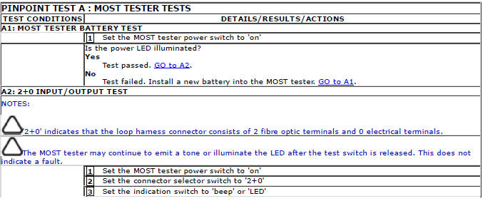
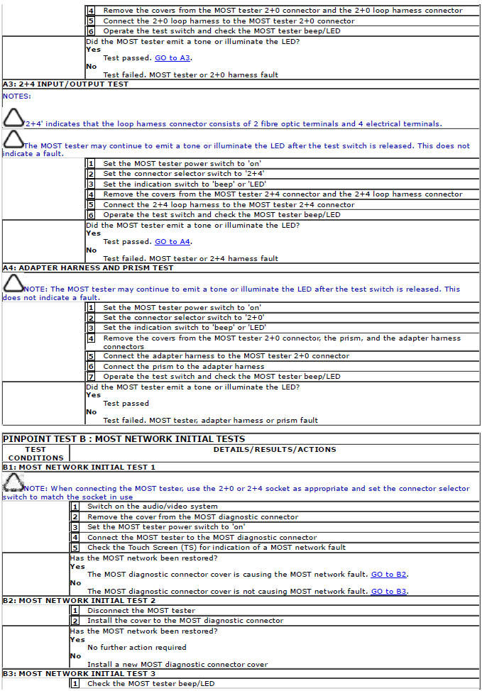
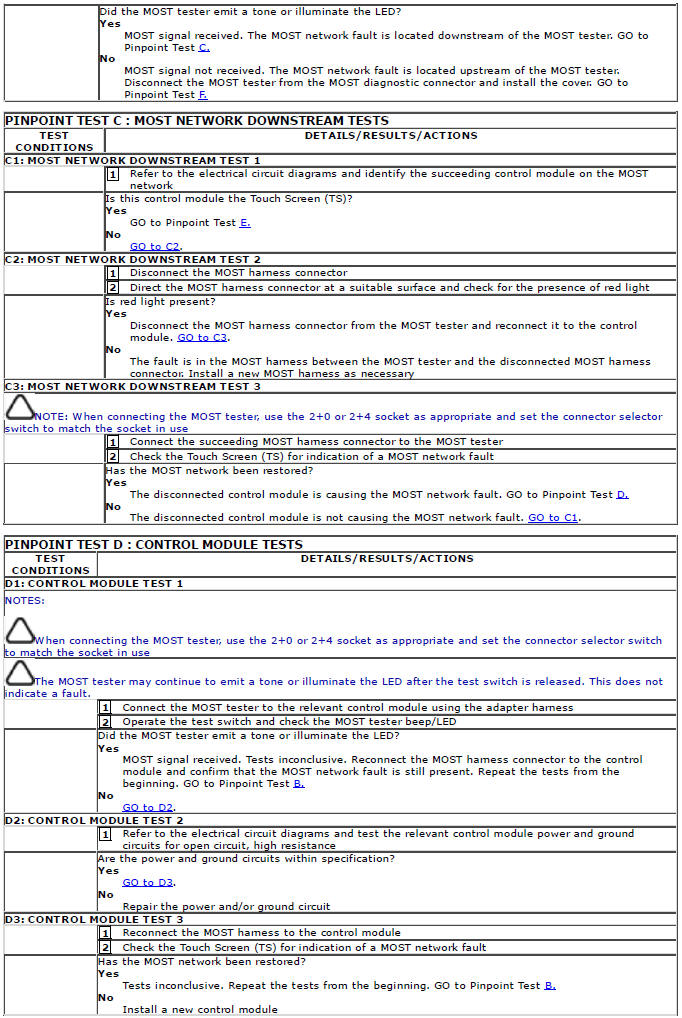
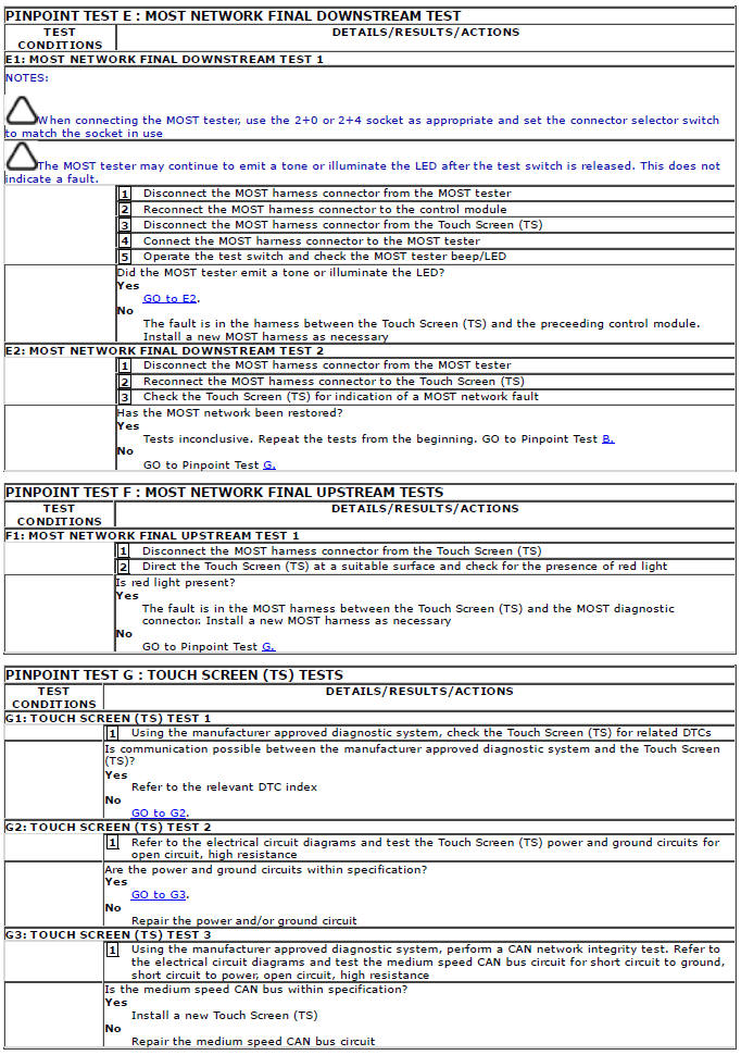
MOST tester. The MOST tester is connected to the MOST network in place of a control module. It will confirm receipt of any existing MOST signal and transmit it to the next control module on the network. Perform the following tests to validate the operation of the MOST tester. GO to Pinpoint Test A.
MOST prism. The MOST prism is connected in the same way as the MOST tester but will simply reflect any existing signal onward to the next control module. Using the MOST prism before or after a long run of harness may cause a ring break as a good signal may be too weak after travelling the extended distance. Also, the MOST prism will pass light in either direction so will not detect reversed MOST terminals elsewhere in the network. For these reasons, the MOST tester is the preferred tool and should be used unless limited access does not permit it
MOST Ring Break Indication
A ring break in the MOST network is indicated by the Touch Screen (TS) soft keys being greyed out and inoperative.
Possible causes of ring breaks are listed in the symptom chart
Pinpoint Tests
DTC Index
For a list of Diagnostic Trouble Codes (DTCs) that could be logged on this vehicle, please refer to Section 100-00.
Module Communications Network
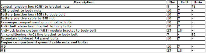
Torque Specifications
READ NEXT:
 Wiring Harness - Description and Operation
Introduction
CAUTION: Do not use any other heat shrink sleeve other than the approved
glue lined heat shrink sleeve mentioned
in the repair procedure.
The purpose of this document is to promote quic
Engine Wiring Harness TD4 2.2L Diesel, Vehicles With:
AWF21 6-Speed Automatic Transmission
Removal
CAUTIONS:
Make sure that the wiring harness is not twisted or damaged on removal. Failure
to follow this instruction may result
in damage to the vehicle.
Take extra care not to damage the wi
SEE MORE:
Engine Wiring Harness TD4 2.2L Diesel, Vehicles With:
AWF21 6-Speed Automatic Transmission
Removal
CAUTIONS:
Make sure that the wiring harness is not twisted or damaged on removal. Failure
to follow this instruction may result
in damage to the vehicle.
Take extra care not to damage the wiring harness clips.
NOTES:
Some variation in the illustrations may occur, but the essential informa
Engine Wiring Harness GTDi 2.0L Petrol
Removal
CAUTIONS:
Make sure that the wiring harness is not twisted or damaged on removal. Failure
to follow this instruction may result
in damage to the vehicle.
Take extra care not to damage the wiring harness clips.
NOTE: Removal steps in this procedure may contain installation details.
1. Disc
