Range Rover Evoque: Control Diagram, System Operation
Control Diagram
NOTE: A = Hardwired; D = High Speed CAN Bus; O = Local Interconnect Network (LIN) Bus
CONTROL DIAGRAM - SHEET 1 OF 2
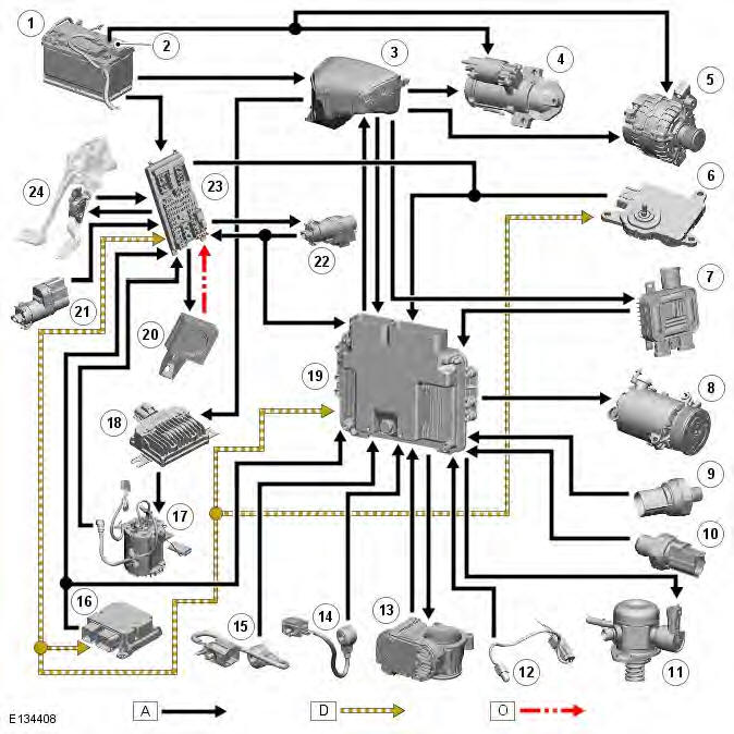
- Battery
- Starter motor fuse
- Battery Junction Box (BJB)
- Starter motor
- Generator
- Transmission Control Module (TCM)
- Cooling fan control module
- Air Conditioning (A/C) compressor clutch
- Low Pressure (LP) fuel sensor
- Oil pressure sensor
- Fuel pump metering valve
- Ambient temperature sensor
- Electric throttle
- Knock sensor
- Knock sensor
- Restraints Control Module (RCM)
- Fuel pump module
- Fuel Pump Driver Module (FPDM)
- Engine Control Module (ECM)
- Immobilizer Antenna Unit (IAU)
- Stop lamp diagnostic switch
- Stop lamp switch
- Central Junction Box (CJB)
- Accelerator Pedal Position (APP) sensor
CONTROL DIAGRAM - SHEET 2 OF 2
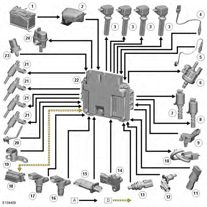
- Battery
- Battery Junction Box (BJB)
- Ignition coil (4 off)
- Pre-catalyst Heated Oxygen Sensor (HO2S)
- Post catalyst HO2S
- Purge valve
- Variable Camshaft Timing (VCT) solenoid (exhaust)
- Variable Camshaft Timing (VCT) solenoid (inlet)
- Turbocharger boost pressure and temperature sensor
- Turbocharger wastegate control solenoid valve
- Air Conditioning (A/C) pressure sensor
- Engine Coolant Temperature (ECT) sensor 2 (NAS only)
- Engine Coolant Temperature (ECT) sensor 1
- Manifold Absolute Pressure (MAP) sensor
- Mass Air Flow (MAF) sensor
- Camshaft Pos tion (CMP) sensor (exhaust)
- Camshaft Pos tion (CMP) sensor (inlet)
- Diagnostic socket
- Crankshaft Position (CKP) sensor
- Engine oil temperature sensor
- Fuel injector (4 off)
- Engine Control Module (ECM)
- Fuel rail pressure sensor
- Diagnostic Monitoring Tank Leakage (DMTL) pump
System Operation
OPERATION
The ECM (engine control module) processes inputs from the following sources:
- BJB (battery junction box)
- Generator
- CJB (central junction box)
- ECT (engine coolant temperature) sensor 1
- ECT sensor 2 (NAS only)
- Immobilizer Antenna Unit (IAU)
- TCM (transmission control module)
- APP (accelerator pedal position) sensor
- Ambient temperature sensor
- LP fuel sensor
- Oil pressure sensor
- CMP (camshaft position) sensor (inlet)
- CMP sensor (exhaust)
- CKP (crankshaft position) sensor
- A/C (air conditioning) pressure sensor
- Front HO2S (heated oxygen sensor)
- Rear HO2S
- Oil temperature sensor
- Fuel rail pressure sensor
- Turbocharger boost pressure and temperature sensor
- MAP (manifold absolute pressure) sensor
- MAF (mass air flow)
- Knock sensors (2 off)
- Stop lamp diagnostic switch
- Stop lamp switch
- RCM (restraints control module)
- A/C compressor clutch
- Electric throttle position sensors.
The ECM outputs controlling signals to the following sensors and actuators:
- FPDM (fuel pump driver module)
- Cooling fan control module
- Fuel injectors
- Fuel pump metering valve
- Turbocharger wastegate control solenoid
- VCT (variable camshaft timing) solenoid (inlet)
- VCT solenoid (exhaust)
- Purge valve
- Ignition coils (4 off)
- Electric throttle motor
- DMTL pump (NAS only).
The ECM is connected to the engine sensors which allow it to monitor the engine operating condit ons. The ECM processes these signals and decides the actions necessary to maintain optimum engine performance in terms of driveability, fuel efficiency and exhaust emissions. The memory of the ECM is programmed with instructions for how to control the engine, this known as the strategy. The memory also contains data in the form of maps which the ECM uses as a basis for fueling and emission control. By comparing the information from the sensors to the data in the maps, the ECM is able to calculate the various output requirements.
The ECM contains an adaptive strategy which updates the system when components vary due to production tolerances or ageing. Some sensors receive a regulated 5 Volt supply from the ECM.
The ECM receives a vehicle speed signal on a CAN (controller area network) bus from the ABS (anti-lock brake system) module. Vehicle speed is an important input to the ECM strategies. The ABS derives the speed signal from the ABS wheel speed sensors. The frequency of this signal changes according to road speed. The ECM uses this signal to determine the following:
- How much to reduce engine torque during gear changes
- When to permit speed control operation
- To control the operation of the speed control system
- Implementation of the dle strategy when the vehicle is stationary.
Ignition is controlled by a direct ignition system, provided by 4 plug top coils. The ECM is able to detect and correct for ignition knock on each cylinder and adjust the ignition timing for each cylinder to achieve optimum performance.
The ECM controls operation of the starter motor via the starter relay in the BJB. The ECM also protects the starter motor, preventing operation of the starter relay if the engine speed signal exceeds a predetermined value The ECM and the CJB exchange encrypted data to validate and approve an engine start.
Refer to: Anti-Theft - Passive (419-01B Anti-Theft - Passive, Description and Operation).
READ NEXT:
 Component Description
DESCRIPTION
Engine Control Module (ECM)
The ECM is located at the rear of the engine compartment, between the
bulkhead and the engine sound insulation. The ECM is located in a plastic molded
carrier
Crankshaft Position (CKP)
Sensor
Special Tool(s)
303-1390A
CKP Sensor Alignment Tool
JLR-303-1595
Alignment Tool, Crankshaft Damper
Removal
NOTE: Removal steps in this procedure may contain installation details.
1. WARNING: Make sure
Catalyst Monitor Sensor
Special Tool(s)
310-121
Wrench, H02S
Removal
WARNING: Observe due care when working near a hot exhaust system.
NOTE: Removal steps in this procedure may contain installation details.
1. WARNING: Make
SEE MORE:
Important information
The information contained in this handbook covers all vehicle derivatives and
optional equipment,
some of which may not be fitted to your vehicle. Due to printing cycles, this
handbook may include
descriptions of options before they become generally available.
The vehicle options, hardware an
Symbols used in this handbook
Safety warnings indicate either a procedure which must be followed
precisely, or
information that should be considered with great care, in order to avoid the
possibility
of personal injury.
Cautions indicate either a procedure which must be followed precisely, or
information that
should
