Range Rover Evoque: Cylinder Head
Removal
NOTES:
Some illustrations may show the engine removed for clarity.
Some variation in the illustrations may occur, but the essential information is always correct.
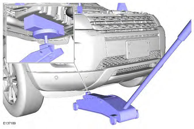
1. Refer to: Battery Tray (414-01 Battery, Mounting and Cables, Removal and Installation).
2. Refer to: Cooling System Draining, Filling and Bleeding (303-03B Engine Cooling - GTDi 2.0L Petrol, General Procedures).
3. Refer to: Camshafts (303-01B Engine - GTDi 2.0L Petrol, Removal and Installation).
4. Refer to: Intake Manifold (303-01B Engine - GTDi 2.0L Petrol, Removal and Installation).
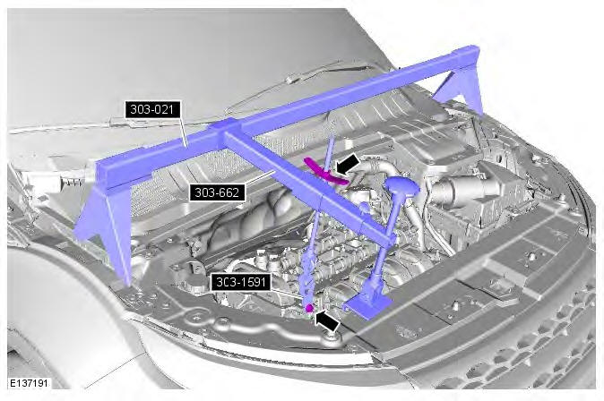
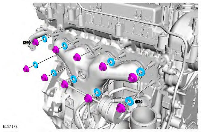
5.
6. Remove the special tool.
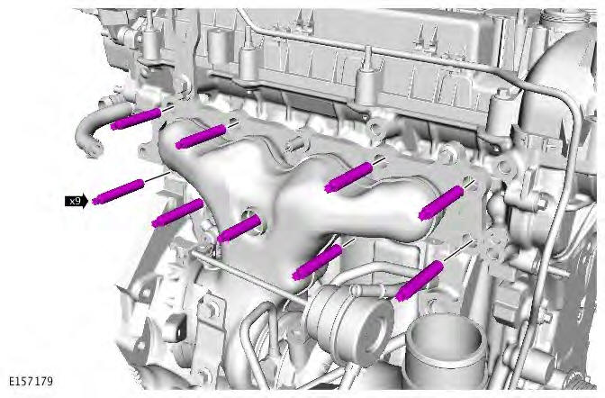
7.
8.
9.
10.
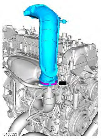
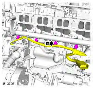
11. CAUTION: Using suitable tie straps, make sure the turbocharger assembly is secure.
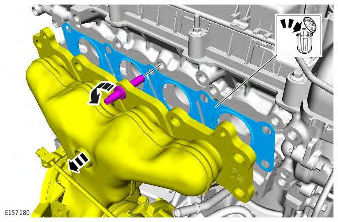
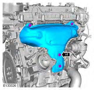
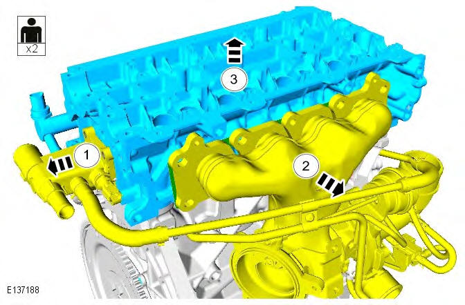
12. CAUTIONS:
Make sure that all openings are sealed. Use new blanking caps.
Be prepared to collect escaping coolant.
- Carefully remove and discard the oil seal.
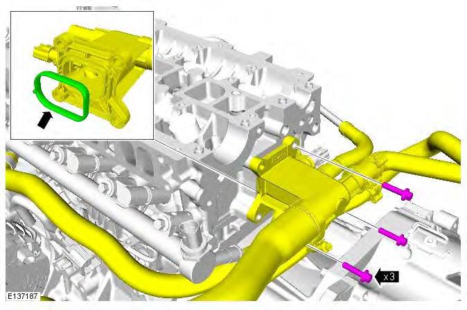
13.
14.
15.
16.
- Remove and discard the cylinder head gasket.

Installation
1.
- Clean the components mating faces.
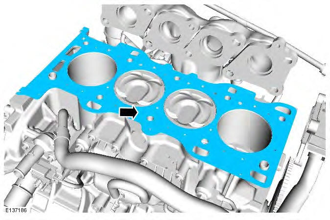
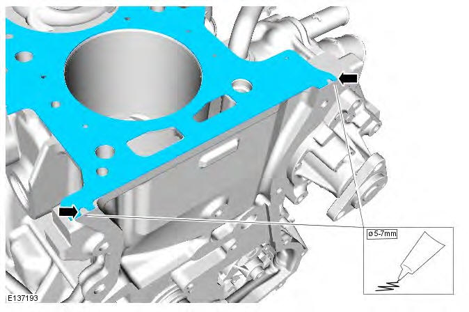
2. CAUTION: Apply sealant WSE-M4G323-A6 in a 5-7mm diameter on both cylinder head gasket notches as shown. The cylinder head and engine front cover must be installed and tightened within 30 minutes of sealant application.
3.
- Clean the component mating faces.

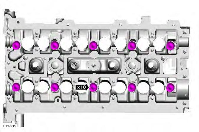
4. CAUTION: Cylinder head bolts may be reused a maximum of two times only.
NOTE: Tighten the bolts in the indicated sequence.
Torque:
- Stage 1: 7 Nm
- Stage 2: 15 Nm
- Stage 3: 55 Nm
- Stage 4: 90
READ NEXT:
Engine Mount LH Removal NOTES: Removal steps in this procedure may contain installation details. Some variation in the illustrations may occur, but the essential information is always correct. 1. Di Engine Mount LH/RH
Removal NOTES: Removal steps in this procedure may contain installation details. Some illustrations may show the engine removed for clarity. 1. WARNING: Make sure to support the vehicle with axle sta Intake Manifold
Removal NOTE: Removal steps in this procedure may contain installation details. 1. WARNING: Make sure to support the vehicle with axle stands. Raise and support the vehicle. 2. Disconnect the battery Oil Cooler
SEE MORE:
WARNINGS: TO AVOID ACCIDENTAL DEPLOYMENT AND POSSIBLE PERSONAL INJURY, THE BACKUP POWER SUPPLY MUST BE DEPLETED BEFORE REPAIRING OR REPLACING ANY AIR BAG SUPPLEMENTAL RESTRAINT SYSTEM (SRS) COMPONENTS. TO DEPLETE THE BACKUP POWER SUPPLY ENERGY, DISCONNECT THE BATTERY GROUND CABLE AND WAIT ONE MI
Restraints
Control Module (RCM)
Rear Differential Control Module (RDCM) CAUTION: Diagnosis by substitution from a donor vehicle is NOT acceptable. Substitution of control modules does not guarantee confirmation of a fault, and may also cause additional faults in the vehicle being tested and/or the donor vehicle. NOT
Active
On-demand Coupling Control Module
