Range Rover Evoque: Intake Manifold
Removal
NOTES:
Removal steps in this procedure may contain installation details.
Some illustrations may show the engine removed for clarity.
1. WARNING: Make sure to support the vehicle with axle stands. Raise and support the vehicle.
2. Disconnect the battery ground cable.
Refer to: Specifications (414-01 Battery, Mounting and Cables, Specifications).
3. Refer to: Engine Cover - GTDi 2.0L Petrol (501-05 Interior Trim and Ornamentation, Removal and Installation).
4.
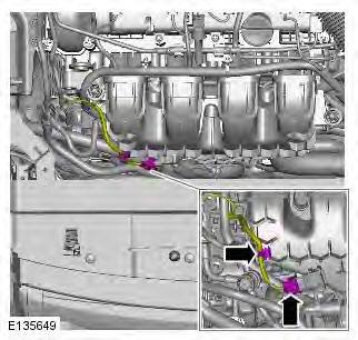
5.
6.
7.
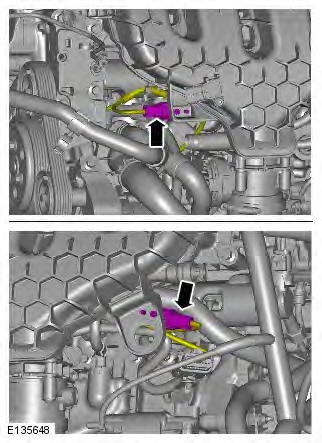
8.
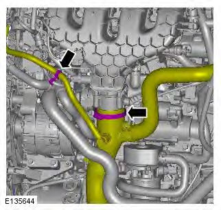
9.
10.
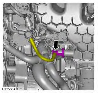
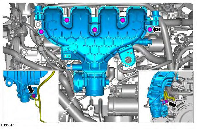
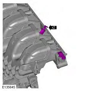
11. NOTE: Do not disassemble further if the component is removed for access only. Torque: 8 Nm
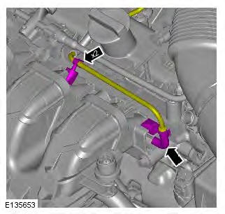
12.
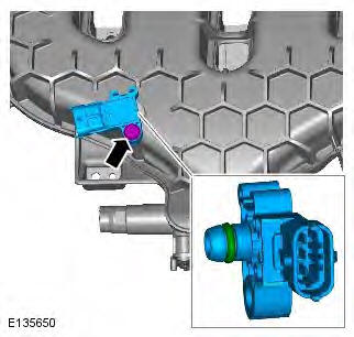
13. Torque: 5 Nm
Installation
1. To install, reverse the removal procedure.
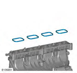
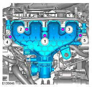
2. CAUTIONS:
Tighten the bolts in the sequence shown.
Make sure that the mating faces are clean and free of foreign material.
Torque: 20 Nm
READ NEXT:
 Oil Cooler
Removal
NOTE: Removal steps in this procedure may contain installation details.
1. WARNING: Make sure to support the vehicle with axle stands.
Raise and support the vehicle.
2. Disconnect the battery
Oil Pan
Removal
NOTES:
Some illustrations may show the engine removed for clarity.
Some variation in the illustrations may occur, but the essential information is
always correct.
Removal steps in this proc
Oil Pump
Removal
NOTES:
Some illustrations may show the engine removed for clarity.
Some variation in the illustrations may occur, but the essential information is
always correct.
Removal steps in this proc
SEE MORE:
Important information
The information contained in this handbook covers all vehicle derivatives and
optional equipment,
some of which may not be fitted to your vehicle. Due to printing cycles, this
handbook may include
descriptions of options before they become generally available.
The vehicle options, hardware an
Symbols used in this handbook
Safety warnings indicate either a procedure which must be followed
precisely, or
information that should be considered with great care, in order to avoid the
possibility
of personal injury.
Cautions indicate either a procedure which must be followed precisely, or
information that
should
