Range Rover Evoque: Floor Console Upper Section
Removal
NOTE: Removal steps in this procedure may contain installation details.
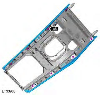
All vehicles
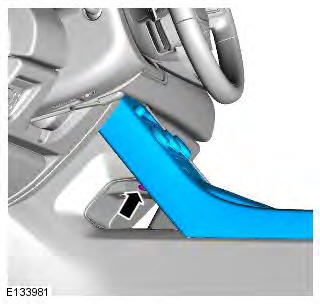
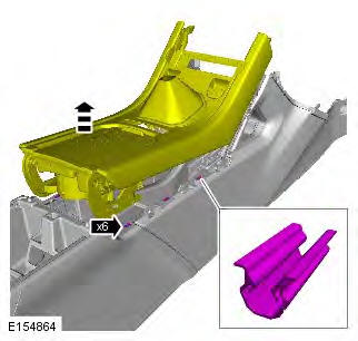
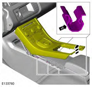
1. CAUTION: The procedure must be carried out on both sides.
NOTE: LH illustration shown, RH is similar.
Torque: 1.9 Nm
Vehicles with manual transmission
2. Refer to: Gearshift Lever Knob (308-06 Manual Transmission/Transaxle External Controls, Removal and Installation).
3. CAUTION: Carefully release the retaining clips.
4.
5. CAUTION: Carefully release the retaining clips.
Vehicles with automatic transmission
6. CAUTION: Carefully release the retaining clips.
7.
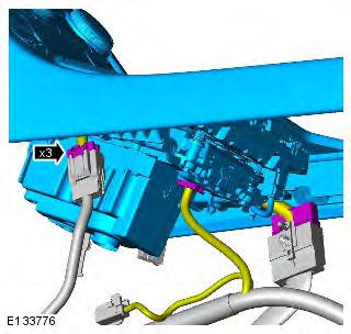
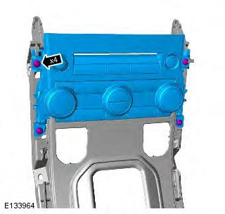
All vehicles
8. NOTE: Do not disassemble further if the component is removed for access only.
Torque:
M5 bolt 1.5 Nm
Screw 1.1 Nm
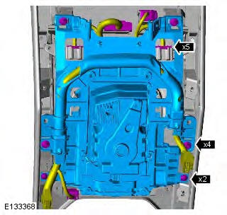
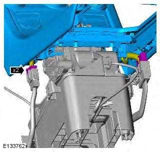
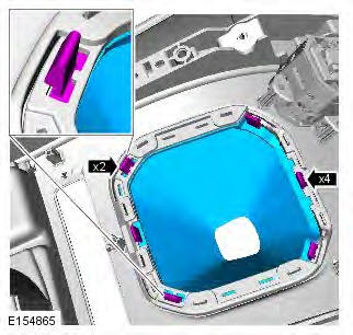
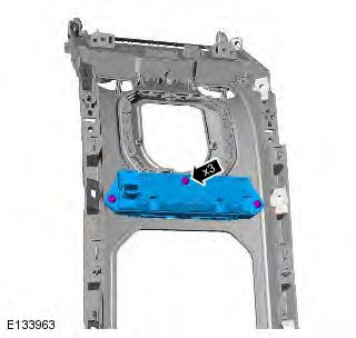
9. Torque: 1.1 Nm
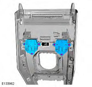
10. Torque: 1.1 Nm
11. Torque: 1.1 Nm
12. Torque: 1.1 Nm
Installation
1. To install, reverse the removal procedure.
2. Connect Land Rover approved diagnostic equipment to vehicle. Read and clear the stored DTCs.
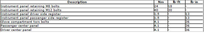
Torque Specifications
READ NEXT:
 Locks, Latches and Entry Systems
Principle of Operation
For a detailed description of the locks, latches and entry systems and
operation, refer to the relevant Description and
Operation section of the workshop manual REFER to: Handl
SEE MORE:
Important information
The information contained in this handbook covers all vehicle derivatives and
optional equipment,
some of which may not be fitted to your vehicle. Due to printing cycles, this
handbook may include
descriptions of options before they become generally available.
The vehicle options, hardware an
Symbols used in this handbook
Safety warnings indicate either a procedure which must be followed
precisely, or
information that should be considered with great care, in order to avoid the
possibility
of personal injury.
Cautions indicate either a procedure which must be followed precisely, or
information that
should
