Range Rover Evoque: Front Halfshaft LH
Special Tool(s)
 205-857
Remover, Halfshaft
Removal
CAUTIONS:
Nuts and bolts must be tightened with the weight of the vehicle on the suspension.
Do not allow halfshafts to hang unsupported at one end or joint damage will occur.
Make sure the halfshaft constant velocity (CV) joints do not over articulate. Failure to follow this instruction may result in damage to the CV joints.
1. WARNING: Make sure to support the vehicle with axle stands. Raise and support the vehicle.
2. Refer to: Wheel and Tire (204-04 Wheels and Tires, Removal and Installation).
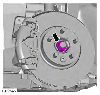
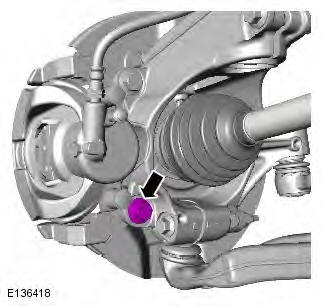
3. CAUTION: Discard the nut.
4.
5. CAUTIONS:
Do not use air tools to remove the nut.
Discard the nut.
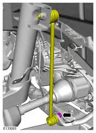
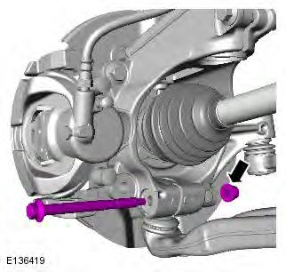
6. CAUTION: Discard the bolt.

7.

8.
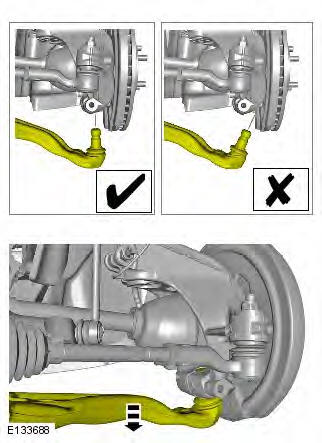
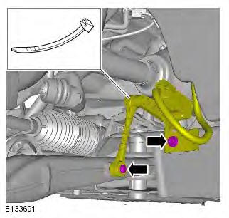
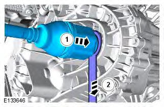
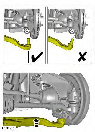
9. CAUTIONS:
Make sure that the driveshaft is supported with suitable retaining straps.
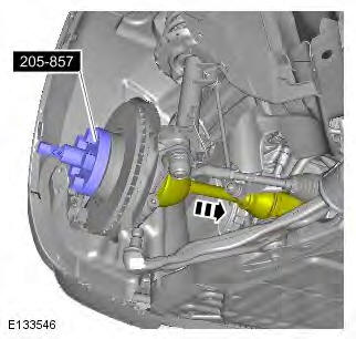
Do not use a hammer to detach the halfshaft from the hub assembly, failure to follow this instruction may result in damage to the halfshaft.
Special Tool(s): 205-857
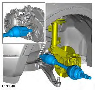
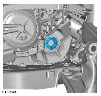
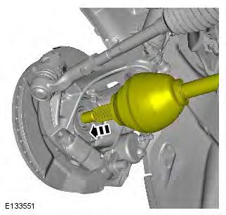
10. WARNING: Be prepared to collect escaping fluids.
CAUTION: Keep the halfshaft horizontal to avoid damaging the oil seal.
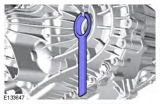
11. CAUTION: Discard the snap ring.
12. CAUTION: Inspect the seal, replace if damaged NOTE: Automatic transmission shown, manual is similar.

Installation
1. NOTES:
Automatic transmission shown, manual is similar.
This step is only required if previously removed.
2. NOTES:
Manual transmission shown, automatic is similar Do not fully engage the halfshaft until the oil seal protector has been removed. To prevent oil seal damage use the protector when installing the shaft into the transmission. It is not a special tool but is available from the Parts Catalogue.
3. CAUTIONS: Make sure that the snap ring is installed from the end of the halfshaft. Failure to follow this instruction may result in damage to the vehicle.
Install a new snap ring.
4. CAUTION: Keep the halfshaft horizontal to avoid damaging the oil seal.
NOTES:
Manual transmission shown, automatic is similar Do not fully engage the halfshaft until the oil seal protector has been removed.
5.
6.
7. Torque: 110 Nm
8. CAUTION: Make sure that a new bolt is installed. Torque: 200 Nm
9. WARNING: Make sure that a new nut is installed.
CAUTIONS:
Do not use air tools to install the nut. Failure to follow this instruction may result in damage to the component.
Install the halfshaft nut finger tight.
Tighten the nut without the weight of the vehicle on the suspension.
Torque:
Stage 1: 120 Nm
Stage 2: 60
READ NEXT:
 Front Halfshaft RH LHD AWD/RHD AWD
Special Tool(s)
205-857
Remover, Halfshaft
Removal
CAUTIONS:
Nuts and bolts must be tightened with the weight of the vehicle on the
suspension.
Do not allow halfshafts to hang unsupported at one end
Inner Constant Velocity (CV) Joint Boot
Special Tool(s)
303-D121
Puller, General Purpose
General Equipment
Vise
Removal
NOTE: RH inner constant velocity joint boot shown, LH is similar.
1. Refer to: Front Halfshaft LH (205-04 Front Drive
Front Halfshaft RH FWD
Special Tool(s)
205-857
Remover, Halfshaft
Removal
CAUTIONS:
Nuts and bolts must be tightened with the weight of the vehicle on the
suspension.
Do not allow halfshafts to hang unsupported at one end
SEE MORE:
Blower Motor LHD AWD/LHD FWD
Special Tool(s)
412-140
Remover/Installer, Blower Motor
Removal
NOTES:
Removal steps in this procedure may contain installation details.
Some variation in the illustrations may occur, but the essential information is
always correct.
1. NOTE: The recirculation blend door must be closed in order for
Blower Motor RHD AWD/RHD FWD, RHD
Special Tool(s)
412-140
Remover/Installer, Blower Motor
Removal
NOTES:
Removal steps in this procedure may contain installation details.
Some variation in the illustrations may occur, but the essential information is
always correct.
All vehicles
1. NOTE: The recirculation blend door must be closed
