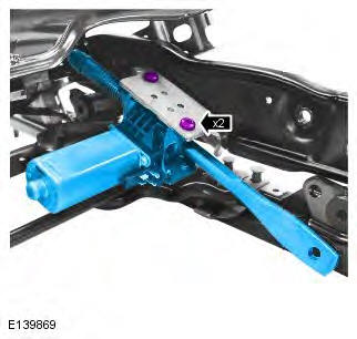
Range Rover Evoque: Front Seat Height Adjustment Motor

Removal

NOTE: Removal steps in this procedure may contain installation details.

All vehicles

1. Disconnect the battery ground cable.

Refer to: Specifications (414-01 Battery, Mounting and Cables, Specifications).

2. WARNING: To avoid accidental deployment, the restraints control module backup power supply must be depleted. Wait at least two minutes after disconnecting the battery ground cable(s) before commencing any repair or adjustment to the supplemental restraint system (SRS), or any component(s) adjacent to the SRS sensors.

Failure to follow these instructions may result in personal injury.

Refer to: Standard Workshop Practices (100-00 General Information, Description and Operation).

3. Refer to: Front Seat Control Switch (501-10 Seating, Removal and Installation).

4. Refer to: Front Seat (501-10 Seating, Removal and Installation).

5. CAUTION: Note the fitted position of the component prior to removal.
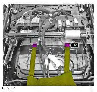
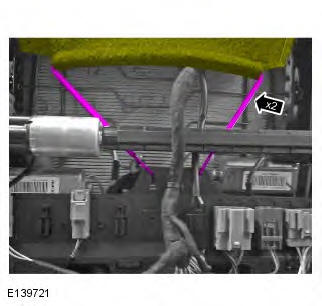
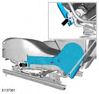
Range Rover Evoque. Front Seat Height Adjustment Motor

Vehicles with sports seats

6.

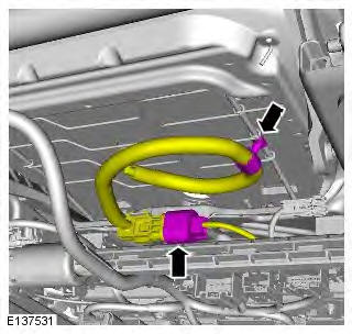
Range Rover Evoque. Front Seat Height Adjustment Motor

7. CAUTION: Note the fitted position of the component prior to removal.
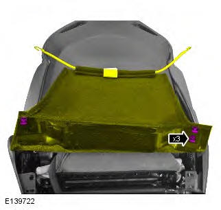
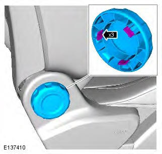
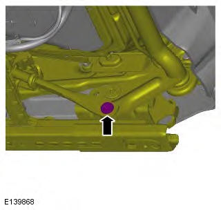
Range Rover Evoque. Front Seat Height Adjustment Motor

Vehicles with heated front seats

8. NOTE: Some variation in the illustrations may occur, but the essential information is always correct.
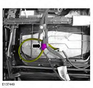
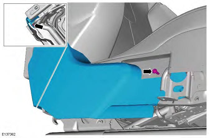
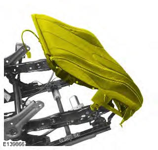
Range Rover Evoque. Front Seat Height Adjustment Motor

Non NAS vehicles

9. CAUTION: Make sure that the component is aligned and attached as shown.
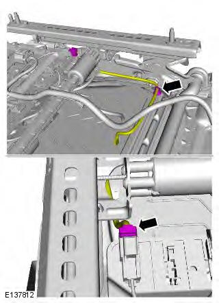
Range Rover Evoque. Front Seat Height Adjustment Motor

NAS vehicles

10.

Range Rover Evoque. Front Seat Height Adjustment Motor

All vehicles

11. NOTE: If equipped.

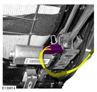
Range Rover Evoque. Front Seat Height Adjustment Motor

12.

Range Rover Evoque. Front Seat Height Adjustment Motor

13.

Range Rover Evoque. Front Seat Height Adjustment Motor

14. NOTE: Some variation in the illustrations may occur, but the essential information is always correct.

Torque: 28 Nm
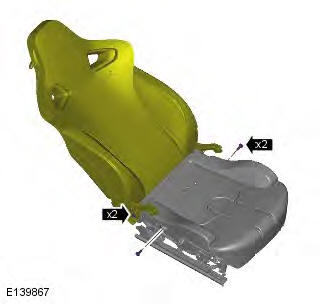
Range Rover Evoque. Front Seat Height Adjustment Motor

15. Torque: 28 Nm

Range Rover Evoque. Front Seat Height Adjustment Motor

16. NOTES:

Use a suitable tool to remove the circlips from the seat cushion frame bolts.

Note the orientation of the components.

Right-hand shown, left-hand similar.

Repeat the procedure for the other side.
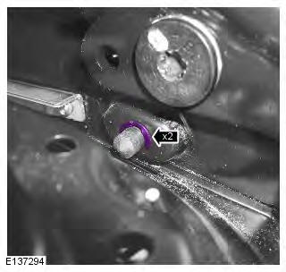
Range Rover Evoque. Front Seat Height Adjustment Motor

17. NOTES:

Right-hand shown, left-hand similar.

Repeat the procedure for the other side.

Torque: 20 Nm
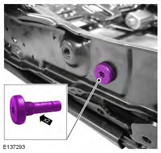
Range Rover Evoque. Front Seat Height Adjustment Motor

18.

Range Rover Evoque. Front Seat Height Adjustment Motor

19. NOTES:

Note the orientation of the components.

Right-hand shown, left-hand similar.
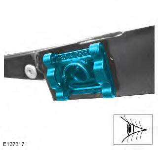
Range Rover Evoque. Front Seat Height Adjustment Motor

20.

Range Rover Evoque. Front Seat Height Adjustment Motor

21. Torque: 10 Nm

Range Rover Evoque. Front Seat Height Adjustment Motor

Installation

1. To install, reverse the removal procedure.

READ NEXT:

 Front Seat Cushion Cover

Removal NOTE: Removal steps in this procedure may contain installation details. All vehicles 1. Prior to carrying out the step by step procedure below, Steps 2 and 3 must be followed for knowledge on

 Rear Seat Cushion Cover

Removal NOTE: Removal steps in this procedure may contain installation details. 1. Prior to carrying out the step by step procedure below, Steps 2 and 3 must be followed for knowledge on how to correc

 Front Seat Backrest Heater Mat

Removal WARNINGS: To avoid accidental deployment and possible personal injury, the backup power supply must be depleted before repairing or replacing any air bag supplemental restraint system (SRS)

SEE MORE:

 Engine Wiring Harness TD4 2.2L Diesel, Vehicles With: AWF21 6-Speed Automatic Transmission

Removal CAUTIONS: Make sure that the wiring harness is not twisted or damaged on removal. Failure to follow this instruction may result in damage to the vehicle. Take extra care not to damage the wiring harness clips. NOTES: Some variation in the illustrations may occur, but the essential informa

 Steering Linkage

Tie Rod End Special Tool(s) 205-754A Splitter, Ball Joints Removal NOTE: RH illustration shown, LH is similar. 1. WARNING: Make sure to support the vehicle with axle stands. Raise and support the vehicle. 2. Refer to: Wheel and Tire (204-04 Wheels and Tires, Removal and Installation). 3. 4. CAUTIO

© 2011-2024 Copyright www.rrevoque.org