Range Rover Evoque: Front Seat Track
Removal
NOTE: Removal steps in this procedure may contain installation details.
All vehicles
1. Disconnect the battery ground cable.
Refer to: Specifications (414-01 Battery, Mounting and Cables, Specifications).
2. WARNING: To avoid accidental deployment and possible personal injury, the backup power supply must be depleted before repairing or replacing any air bag supplemental restraint system (SRS) components. To deplete the backup power supply energy, disconnect the battery ground cable and wait one minute. Failure to follow this instruction may result in personal injury.
Refer to: Standard Workshop Practices (100-00 General Information, Description and Operation).
3. Refer to: Front Seat (501-10 Seating, Removal and Installation).
4. Refer to: Front Seat Control Switch (501-10 Seating, Removal and Installation).
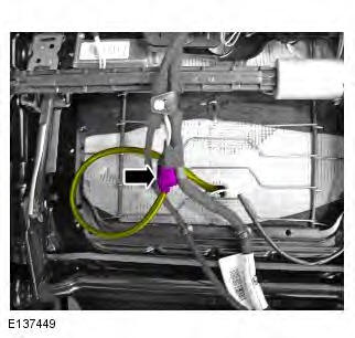
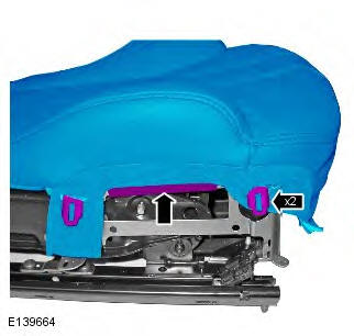
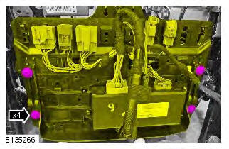
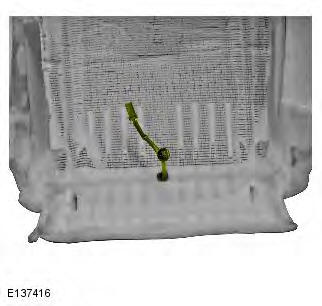
5. CAUTION: Note the fitted position of the component prior to removal.
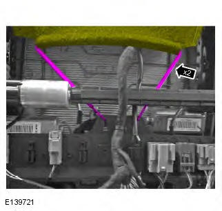
6.
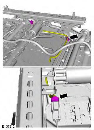
7.
8.
Vehicles with heated front seats
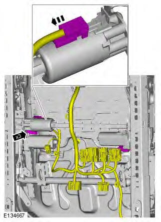
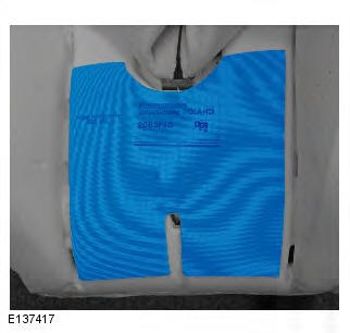
9. NOTE: Some variation in the illustrations may occur, but the essential information is always correct.
Non NAS vehicles
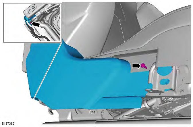
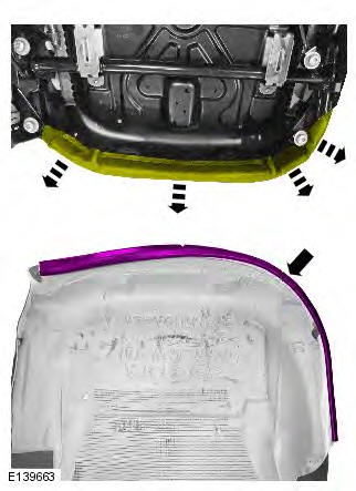
10. CAUTION: Make sure the component is aligned as shown.
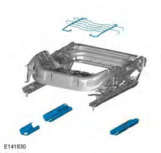
All vehicles
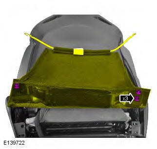
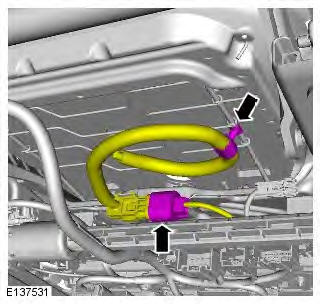
11.
12.
13.
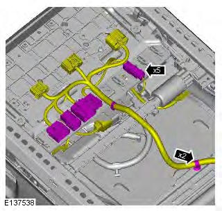
NAS vehicles
14.
15.
All vehicles
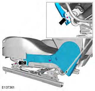
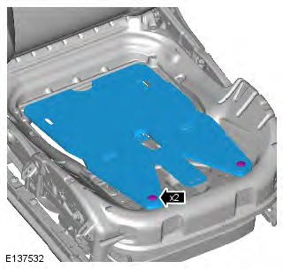
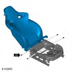
16.
17. Torque: 10 Nm
18.
19. Torque: 28 Nm
20.
Installation
1. To install, reverse the removal procedure.
Front Seat Backrest Cushion
Removal
WARNINGS:
To avoid accidental deployment and possible personal injury, the backup power supply must be depleted before repairing or replacing any air bag supplemental restraint system (SRS) components. To deplete the backup power supply energy, disconnect the battery ground cable and wait one minute. Failure to follow this instruction may result in personal injury.
Never probe the electrical connectors of air bag modules or any other supplemental restraint system component.
Failure to follow this instruction may result in personal injury.
NOTE: Removal steps in this procedure may contain installation details.
All vehicles
1. Disconnect the battery ground cable.
Refer to: Specifications (414-01 Battery, Mounting and Cables, Specifications).
2. Refer to: Standard Workshop Practices (100-00 General Information, Description and Operation).
3. Refer to: Front Seat Backrest Cover (501-10 Seating, Removal and Installation).
Vehicles with heated front seats
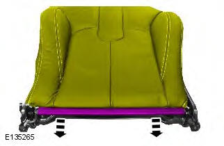
4.
5.
Installation
1. To install, reverse the removal procedure.
READ NEXT:
 Heater Mats
Principles of Operation
Heated seats incorporate heater elements in the cushion and the backrest of
the seat. Each cushion heater element has a
thermal sensor, which supplies a feedback temperature s
Passenger Seat Cushion Heater Mat
Removal
WARNINGS:
To avoid accidental deployment and possible personal injury, the backup
power supply must be depleted before
repairing or replacing any air bag supplemental restraint system (SRS)
Front Seat Tilt Assembly
Removal
WARNINGS:
To avoid accidental deployment and possible personal injury, the backup
power supply must be depleted before
repairing or replacing any air bag supplemental restraint system (SRS)
SEE MORE:
Important information
The information contained in this handbook covers all vehicle derivatives and
optional equipment,
some of which may not be fitted to your vehicle. Due to printing cycles, this
handbook may include
descriptions of options before they become generally available.
The vehicle options, hardware an
Symbols used in this handbook
Safety warnings indicate either a procedure which must be followed
precisely, or
information that should be considered with great care, in order to avoid the
possibility
of personal injury.
Cautions indicate either a procedure which must be followed precisely, or
information that
should
