Range Rover Evoque: Heating and Ventilation
Component Location
COMPONENT LOCATION
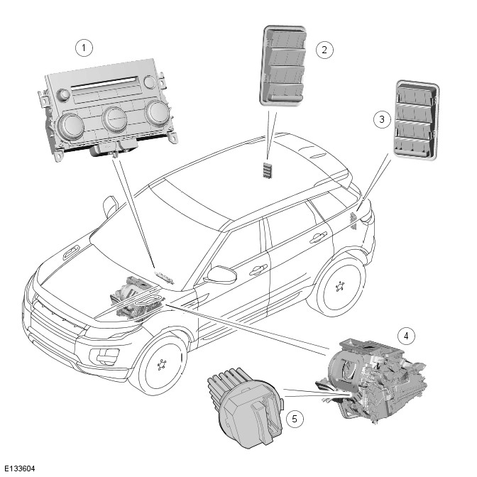
- ATC (automatic temperature control)
- RH (right-hand) ventilation outlet
- LH (left-hand) ventilation outlet
- Heater assembly
- Blower motor control module
Overview
OVERVIEW
Two levels of heating and ventilation are available. Standard specification vehicles are fitted with a dual zone automatic system, which can provide different temperature settings for the LH (left-hand) and RH (right-hand) sides of the cabin. The dual zone system may also be fitted with a pollution sensor to control the quality of air in the cabin. The higher specification also offers a cool face option for rear passengers through the rear face vents fitted in the centre console.
The heater assembly for both systems is installed on the vehicle center line, between the instrument panel and the engine bulkhead as part of the cockpit assembly.
The ATC module controls operation of the blower motor via the blower motor control module, which is mounted on the bulkhead side of the heater assembly casing. For additional information, refer to:
- Air Distribution and Filtering (412-01 Climate Control, Description and Operation),
- Air Conditioning (412-01 Climate Control, Description and Operation),
- Control Components (412-01 Climate Control, Description and Operation),
- Electric Booster Heater (412-02 Auxiliary Climate Control, Description and Operation),
- Fuel Fired Booster Heater - AWD (412-02 Auxiliary Climate Control, Description and Operation).
System Operation and Component Description
System Operation
Refer to: Heating and Ventilation (412-01 Climate Control, Description and Operation).
Component Description
AUTOMATIC TEMPERATURE CONTROL MODULE
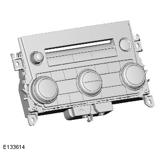
Air distribution and temperature is controlled by the ATC (automatic temperature control) module, which is integral with the control panel. In response to commands from the control panel, the ATC module controls operation of 5 stepper motors mounted on the heater assembly casing.
Refer to: Control Components (412-01 Climate Control, Description and Operation).
HEATER ASSEMBLY
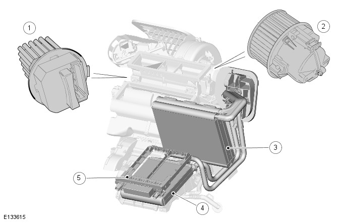
- Blower motor control module
- Blower motor
- A/C (air conditioning) evaporator
- Heater core
- Electric booster heater
The heater assembly controls the temperature of the air supplied to the air distribution ducts, as directed by the ATC module. The heater assembly is mounted on the vehicle center line and comprises the following components:
- Blower motor
- Heater core
- Cabin air filter
Refer to: Air Distribution and Filtering (412-01 Climate Control, Description and Operation). - A/C evaporator
Refer to: Air Conditioning (412-01 Climate Control, Description and Operation). - Air intake flap and stepper motor
Refer to: Air Conditioning (412-01 Climate Control, Description and Operation). - Air distribution flaps and stepper motors
Refer to: Control Components (412-01 Climate Control, Description and Operation). - Temperature blend flaps and stepper motors
Refer to: Control Components (412-01 Climate Control, Description and Operation). - Electric booster heater (if fitted).
Refer to: Electric Booster Heater (412-02 Auxiliary Climate Control, Description and Operation).
Blower Motor
The blower motor comprises an open hub, centrifugal fan powered by an electric motor. Operation of the blower motor is controlled by the ATC module in conjunction with the blower motor control module. The ATC module provides a PWM (pulse width modulation) signal to the blower motor control module based on the required blower speed. The blower motor control module interprets the PWM signal as a blower motor speed and controls the voltage to the blower motor accordingly.
Refer to: Control Components (412-01 Climate Control, Description and Operation).
Heater Core
The heater core provides the heat source to warm the air being supplied into the cabin. The heater core is an aluminum, 2 pass, fin and tube heat exchanger installed across the width of the heater assembly. Two aluminum tubes attached to the heater core extend through the engine bulkhead and connect to the engine cooling system. When the engine is running, engine coolant is constantly circulated through the heater core by the coolant pump.
Refer to: Engine Cooling - AWD (303-03A Engine Cooling - TD4 2.2L Diesel, Description and Operation) / Engine Cooling (303-03B Engine Cooling - GTDi 2.0L Petrol, Description and Operation).
VENTILATION OUTLETS
The ventilation outlets allow the free flow of air through the cabin. The outlets are installed in the LH (left-hand) and RH (right-hand) rear quarter panels, behind the tail lamps.
Each ventilation outlet comprises a grille covered by a soft rubber flap, and is effectively a non-return valve. The flaps open and close automatically depending on the differential between cabin and outside air pressures.
PRINCIPLES OF OPERATION
Operation of the heating and ventilation system is controlled by the ATC module.
Refer to: Control Components (412-01 Climate Control, Description and Operation).
READ NEXT:
 Air Conditioning
Component Location
COMPONENT LOCATION
High pressure line
Low pressure servicing connection
High pressure servicing connection
Thermostatic expansion valve
Evaporator
Refrigerant pressure senso
Control Components - Component Location
Component Location
COMPONENT LOCATION (GTDI)
Refrigerant pressure sensor
Cabin humidity sensor (if fitted)
A/C (air conditioning) compressor
ECT (engine coolant temperature) sensor
Ambient air
SEE MORE:
Important information
The information contained in this handbook covers all vehicle derivatives and
optional equipment,
some of which may not be fitted to your vehicle. Due to printing cycles, this
handbook may include
descriptions of options before they become generally available.
The vehicle options, hardware an
Symbols used in this handbook
Safety warnings indicate either a procedure which must be followed
precisely, or
information that should be considered with great care, in order to avoid the
possibility
of personal injury.
Cautions indicate either a procedure which must be followed precisely, or
information that
should
