Range Rover Evoque: Instrument Panel Upper Section
Removal
NOTE: Removal steps in this procedure may contain installation details.
1. Disconnect the battery ground cable.
Refer to: Specifications (414-01 Battery, Mounting and Cables, Specifications).
2. Make the SRS system safe.
Refer to: Standard Workshop Practices (100-00 General Information, Description and Operation).
3. NOTE: The procedure must be carried out on both sides. Refer to: A-Pillar Trim Panel (501-05 Interior Trim and Ornamentation, Removal and Installation).
4. Refer to: Steering Column (211-04 Steering Column, Removal and Installation).
5. Refer to: Floor Console Upper Section (501-12 Instrument Panel and Console, Removal and Installation).
6. Refer to: Glove Compartment (501-12 Instrument Panel and Console, Removal and Installation).
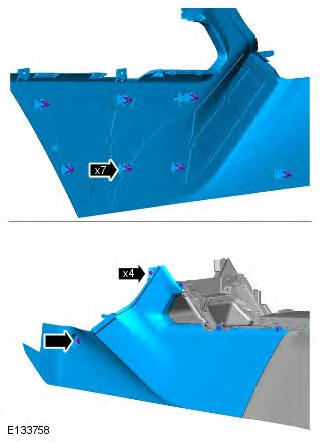
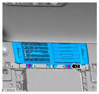
7. NOTES:
The step must be carried out on both sides.
LH illustration shown, RH is similar.
Torque:
Screw 17mm 1.9 Nm
Screw 13mm 1.1 Nm
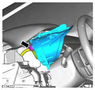
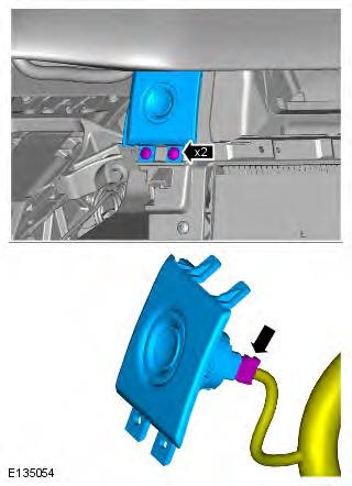
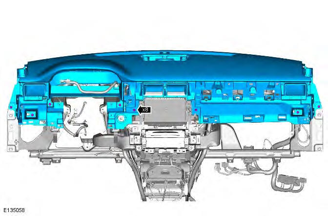
8.
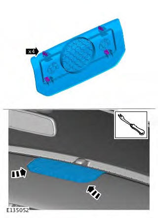
9. Torque: 1 Nm
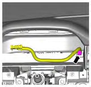
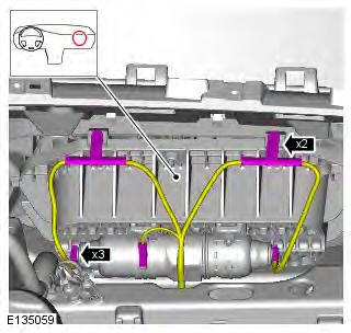
10.
11. Torque: 1.5 Nm

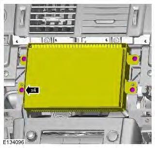
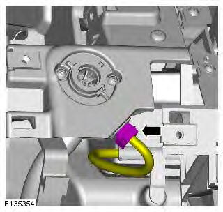
12. CAUTION: Take extra care not to damage the instrument cluster face.
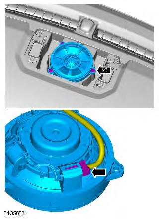
13.
14. Torque: 6 Nm
15.
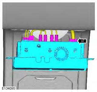
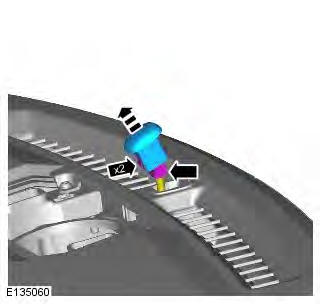
16. CAUTION: Care must be taken to avoid damage to the internal components of the center registers.
Torque: 1.5 Nm
17. Torque: 1.5 Nm
18.
19.
20. Torque: 6 Nm
21. CAUTION: Protect the surrounding trim to avoid damage.
NOTE: With assistance remove the component.
Torque: 6 Nm
Installation
1. To install, reverse the removal procedure.
READ NEXT:
 Floor Console
Removal
NOTE: Removal steps in this procedure may contain installation details.
1. Refer to: Floor Console Upper Section (501-12 Instrument Panel and
Console, Removal and Installation).
2. NOTES:
The
Overhead Console
Removal
NOTE: Removal steps in this procedure may contain installation details.
1. CAUTION: Take extra care not to damage the
edges of the component.
2.
3. NOTE: Do not disassemble further if the
co
Floor Console Upper Section
Removal
NOTE: Removal steps in this procedure may contain installation details.
All vehicles
1. CAUTION: The procedure must be carried out on
both sides.
NOTE: LH illustration shown, RH is similar.
T
SEE MORE:
Important information
The information contained in this handbook covers all vehicle derivatives and
optional equipment,
some of which may not be fitted to your vehicle. Due to printing cycles, this
handbook may include
descriptions of options before they become generally available.
The vehicle options, hardware an
Symbols used in this handbook
Safety warnings indicate either a procedure which must be followed
precisely, or
information that should be considered with great care, in order to avoid the
possibility
of personal injury.
Cautions indicate either a procedure which must be followed precisely, or
information that
should
