Range Rover Evoque: Overhead Console
Removal
NOTE: Removal steps in this procedure may contain installation details.
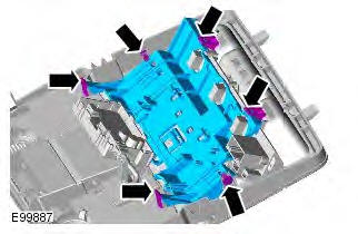
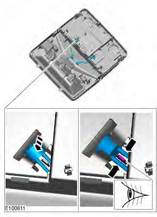
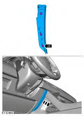
1. CAUTION: Take extra care not to damage the edges of the component.
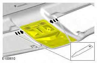
2.
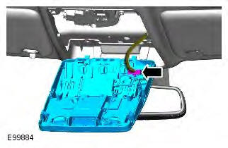
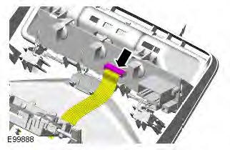
3. NOTE: Do not disassemble further if the component is removed for access only.
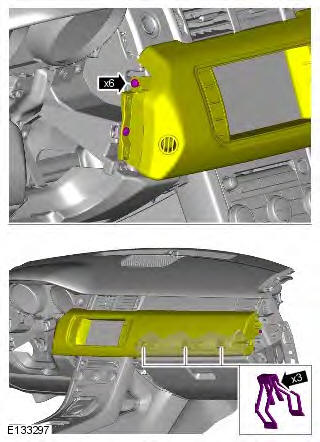
4. CAUTION: Take extra care not to damage the wiring harnesses.
Take precautions to avoid any electrostatic charging, which could damage this comopnent.
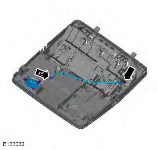
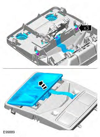
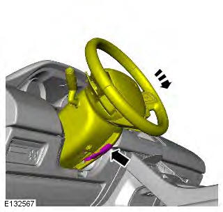
5.
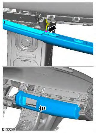
6. CAUTION: Take extra care not to damage the wiring harnesses.
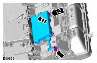
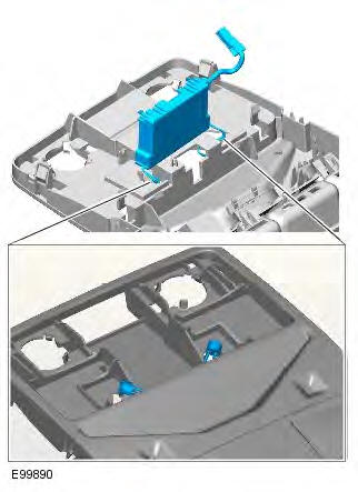
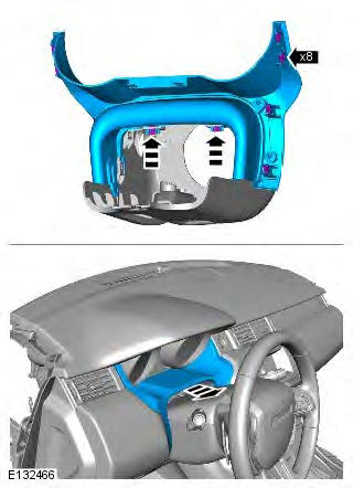
7.
8.
Installation
1. CAUTION: Take extra care not to damage the wiring harnesses.
NOTE: If installing a new overhead console, make sure the original blanking plugs are installed to the new component.
To install, reverse the removal procedure.
Glove Compartment
Removal
NOTE: Removal steps in this procedure may contain installation details.
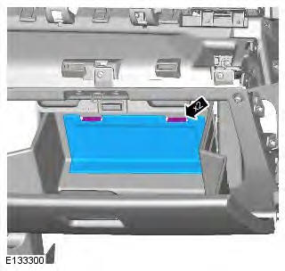
1.
2.
3.
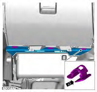
4. NOTES:
Left-hand shown, right-hand similar.
The step must be carried out on both sides.
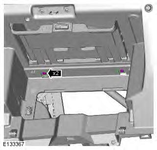
5.
6. Torque: 4 Nm
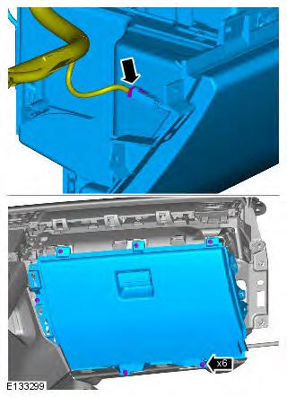
7.
8.
9. NOTE: Glove compartment shown removed for clarity.
10. Torque: 6 Nm
Installation
1. To install, reverse the removal procedure.
READ NEXT:
 Floor Console Upper Section
Removal
NOTE: Removal steps in this procedure may contain installation details.
All vehicles
1. CAUTION: The procedure must be carried out on
both sides.
NOTE: LH illustration shown, RH is similar.
T
Locks, Latches and Entry Systems
Principle of Operation
For a detailed description of the locks, latches and entry systems and
operation, refer to the relevant Description and
Operation section of the workshop manual REFER to: Handl
SEE MORE:
Important information
The information contained in this handbook covers all vehicle derivatives and
optional equipment,
some of which may not be fitted to your vehicle. Due to printing cycles, this
handbook may include
descriptions of options before they become generally available.
The vehicle options, hardware an
Symbols used in this handbook
Safety warnings indicate either a procedure which must be followed
precisely, or
information that should be considered with great care, in order to avoid the
possibility
of personal injury.
Cautions indicate either a procedure which must be followed precisely, or
information that
should
