Range Rover Evoque: Intake Air Distribution and Filtering - GTDi 2.0L Petrol
Intake Air Distribution and Filtering - Component Location
COMPONENT LOCATION
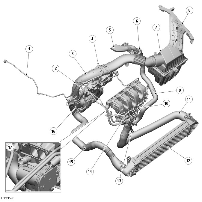
- Purge hose from charcoal canister
- Clean air purge hose
- Clean air inlet ducts
- Camshaft cover vent pipe connection
- Sound generator duct
- Sound generator
- Air cleaner housing
- Dirty air intake duct
- Sound generator hose
- Intake manifold
- Cool intake air hose from charge air cooler
- Charge air cooler
- Clean air purge 2 hose
- Vapor purge 3 hose from purge valve
- Hot intake air hose from turbocharger
- Turbocharger
- Crankcase ventilation hose connection
Intake Air Distribution and Filtering - Overview
OVERVIEW
The intake air distribution system comprises:
- Manifold Absolute Pressure (MAP) sensor
- Air cleaner assembly
- Charge air cooler
- Turbocharger
- Intake manifold.
Intake Air Distribution and Filtering - System Operation and Component Description
System Operation
OPERATION
Ambient air is drawn into the intake air system through the dirty air duct located in the LH (left-hand) front fender. The air passes through the duct and into the bottom of the air cleaner assembly. The air is filtered through a pleated paper filter to remove particulate matter. The clean air from the filter passes through a tube in the air cleaner damper chamber and passes through a MAF (mass air flow) sensor before entering the clean air duct to the turbocharger. The MAF sensor measures the air flow into the turbocharger and engine.
At the turbocharger the clean air is compressed by the turbine compressor impeller. The hot, compressed air is passed from the turbocharger through a hose to the charge air cooler. The air is cooled which increases it density and passed from the charge air cooler to the electric throttle which controls the amount of air entering the intake manifold. The electric throttle is controlled by the ECM (engine control module) which controls the position of the throttle butterfly to allow the correct amount of air into the intake manifold. A MAP (manifold absolute pressure) sensor, located in the intake manifold, measures the air pressure in the manifold and is used by the ECM in conjunction with the MAF sensor to calculate pressure and density of the air entering the engine.
Component Description
DESCRIPTION
Air Cleaner and Ducting Assembly
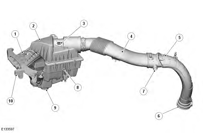
- Dirty air intake duct
- Air cleaner housing damper
- Mass Air Flow (MAF) sensor
- Clean air duct - upper
- Clean air duct - lower
- Clean inlet to turbocharger
- Hose connection for camshaft cover vent
- Air cleaner base
- Water drain valve
- Dirty air inlet
The air cleaner assembly is located on the LH side of the engine compartment. The assembly is located in 2 rubber grommets in brackets on the LH engine mount and secured with a bolt to the hood closing panel.
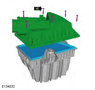
The air cleaner lid is secured with 6 screws which are removed to access the paper air filter element.
A plastic moulded upper low pressure duct is attached to the air cleaner housing damper and secured with a worm drive clamp. A second lower low pressure duct is attached to the upper duct and secured with a clamp. The lower duct is attached to the clean air intake on the turbocharger and is also secured with a clamp.
The air cleaner housing provides the location for the MAF sensor.
Refer to: Electronic Engine Controls (303-14B Electronic Engine Controls - GTDi 2.0L Petrol, Description and Operation).
Intake Manifold
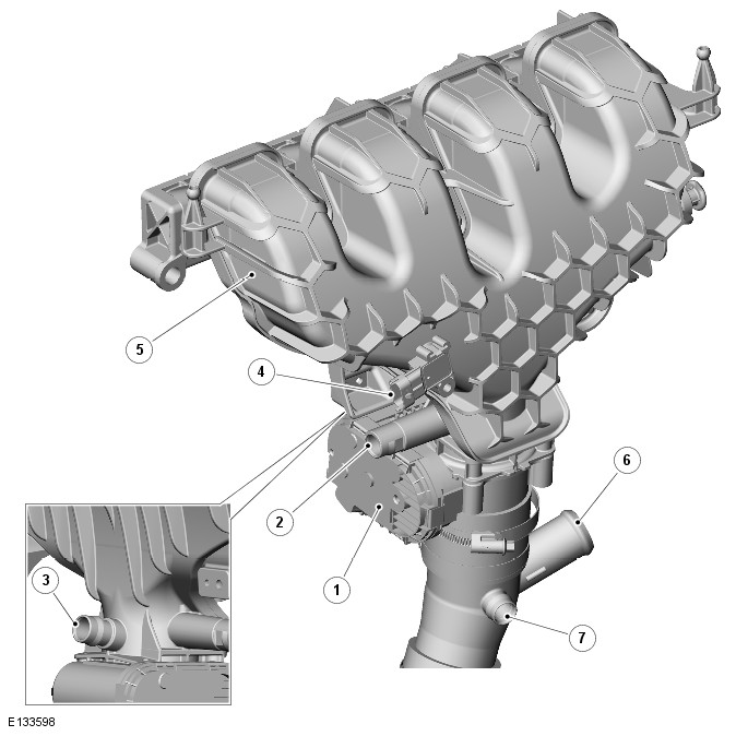
- Electric throttle
- Vapor purge 3 hose from purge valve connection
- Crankcase ventilation hose connection
- Mass Air Pressure (MAP) sensor
- Intake manifold
- Sound generator hose connection
- Clean air purge 2 hose connection
The molded plastic intake manifold is attached to the cylinder head with 5 screws and each cylinder intake is sealed with a shaped seal ring.
The manifold has a connection for the vacuum pipe to the turbocharger, a connection for crankcase breather hose and a connection for the purge 3 hose from the purge valve. The lower part of the manifold has 4 threaded holes to provide for the attachment of the electric throttle which is secured with 4 screws and sealed with a flexible seal ring.
A molded connector is attached to the base of the electric throttle with a short section of hose which is secured to both components with worm drive clamps. The connector allows for the high pressure intake air hose from the charge air cooler to be attached and also allows for the attachment of the clean air purge 2 hose and also the sound generator hose.
The sound generator comprises a hose connected to the connector pipe attached to the electric throttle, a sound generator assembly and ducting to the passenger compartment. Intake noise is transmitted from the air intake through the hose to the sound generator. The sound is modified by a membrane in the sound generator and the rich engine induction sound is passed to the passenger compartment interior when the vehicle is under hard acceleration.
The electric throttle is detailed in Electronic Engine Controls Refer to: Electronic Engine Controls (303-14B Electronic Engine Controls - GTDi 2.0L Petrol, Description and Operation).
Intake Air Distribution and Filtering - GTDi 2.0L Petrol
Torque Specifications

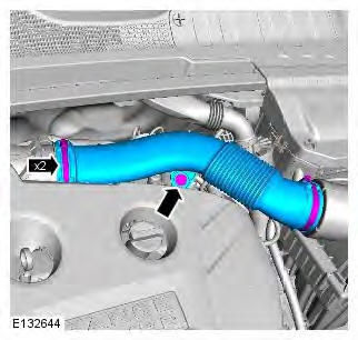
Air Cleaner Intake Pipe
Removal
NOTES:
Some variation in the illustrations may occur, but the essential information is always correct.
Removal steps in this procedure may contain installation details.
1. Refer to: Engine Cover - GTDi 2.0L Petrol (501-05 Interior Trim and Ornamentation, Removal and Installation).
2.
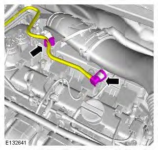
3. Torque:
- M6 Bolt 10 Nm
- Retaining clamps 3 Nm
Installation
1. To install, reverse the removal procedure.
Air Cleaner
Removal
NOTES:
Some variation in the illustrations may occur, but the essential information is always correct.
Removal steps in this procedure may contain installation details.
1. Torque: 3 Nm
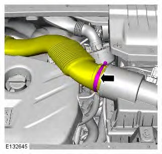
2. Torque: 10 Nm
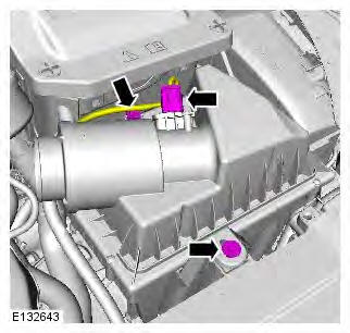
3.
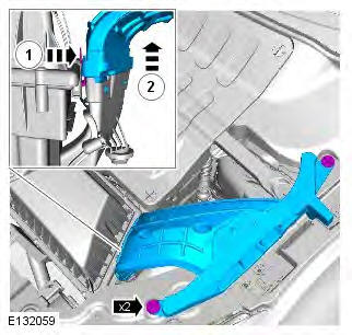
4.
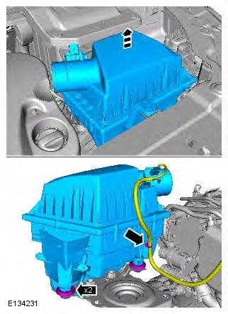
5. Torque: 1.6 Nm
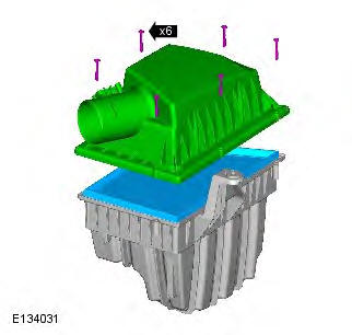
Installation
1. To install, reverse the removal procedure.
Air Cleaner Element
Removal
NOTE: Removal steps in this procedure may contain installation details.
1. Torque: 3 Nm
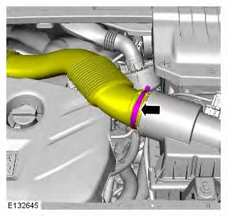
2.
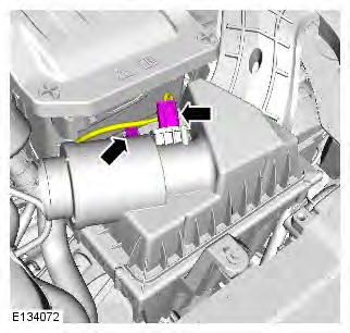
3. Torque: 1.6 Nm
Installation
1. To install, reverse the removal procedure.
Intake Air Distribution and Filtering
Principles of Operation
For additional information on the operation of intake air distribution and filtering, refer to the relevant workshop manual section. REFER to: (303-12B Intake Air Distribution and Filtering - GTDi 2.0L Petrol)
Inspection and verification
CAUTION: Diagnosis by substitution from a donor vehicle is NOT acceptable. Substitution of control modules does not guarantee confirmation of a fault and may also cause additional faults in the vehicle being checked and/or the donor vehicle.
NOTE: Check and rectify basic faults before beginning diagnostic routines involving pinpoint tests.
1. Verify the customer concern.
2. Visually inspect for obvious mechanical or electrical faults.
Visual Inspection

3. If an obvious cause for an observed or reported concern is found, correct the cause (if possible) before proceeding to the next step.
4. Use the approved diagnostic system or a scan tool to retrieve any diagnostic trouble codes (DTCs) before moving onto the symptom chart or DTC index.
- Make sure that all DTCs are cleared following rectification.
Symptom chart

Charge Air Cooler
Removal
CAUTION: Make sure that all openings are sealed. Use new blanking caps.
NOTES:
Removal steps in this procedure may contain installation details.
Some variation in the illustrations may occur, but the essential information is always correct.
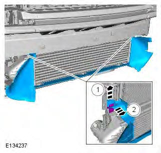
1. Refer to: Front Bumper Cover (501-19 Bumpers, Removal and Installation).
2.
3.
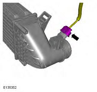
4. Torque: 5 Nm
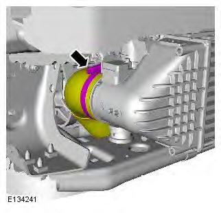
5. Torque: 5 Nm
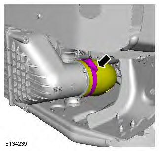
6. Torque: 5 Nm
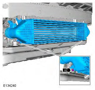
7. CAUTION: The O-ring seal is to be reused unless damaged. Torque: 4 Nm
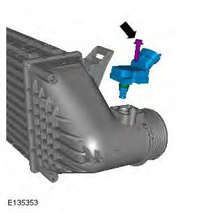
Installation
1. To install, reverse the removal procedure.
Charge Air Cooler Intake Pipe
Removal
CAUTION: Make sure that all openings are sealed. Use new blanking caps.
NOTES:
Some variation in the illustrations may occur, but the essential information is always correct.
Removal steps in this procedure may contain installation details.
1. WARNING: Do not work on or under a vehicle supported only by a jack. Always support the vehicle on safety stands. Raise and support the vehicle.
2. NOTE: Repeat the above step for the other side. Refer to: Fender Splash Shield (501-02 Front End Body Panels, Removal and Installation).
3. Refer to: Front Bumper Cover (501-19, Removal and Installation).
4.
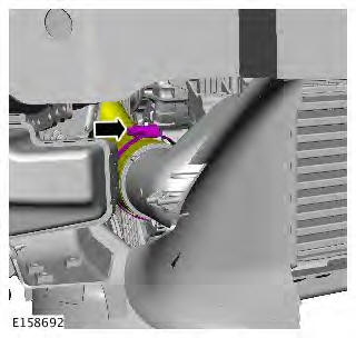
5. Refer to: Engine Lower Support Insulator (303-01B Engine - GTDi 2.0L Petrol, Removal and Installation).
6. NOTE: Some components shown removed for clarity.
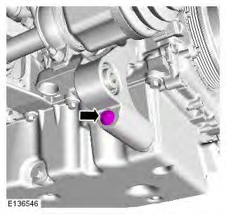
7. NOTE: Some components shown removed for clarity.
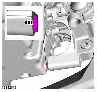
8. Refer to: Front Halfshaft RH - LHD AWD/RHD AWD (205-04 Front Drive Halfshafts, Removal and Installation).
9.
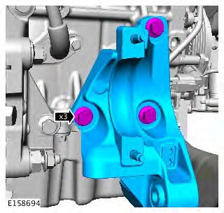
10.
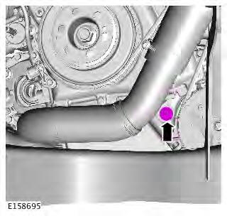
11.
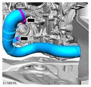
Installation
1. Torque:
- Clip 5 Nm
- M8 Nut 25 Nm
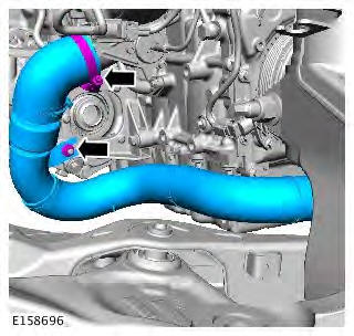
2. Torque: 25 Nm
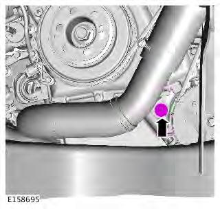
3. Torque: 65 Nm
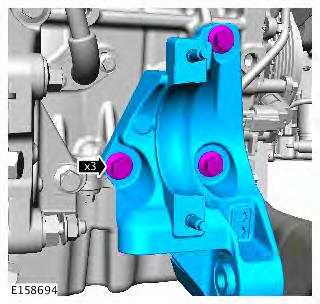
4. Refer to: Front Halfshaft RH - LHD AWD/RHD AWD (205-04 Front Drive Halfshafts, Removal and Installation).
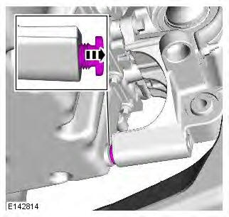
5. NOTE: Some components shown removed for clarity. Torque: 4 Nm
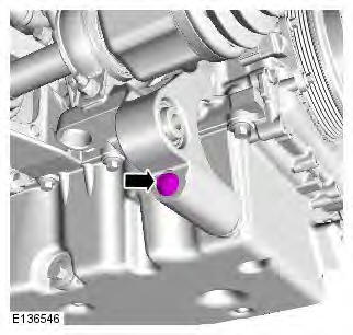
6. NOTE: Some components shown removed for clarity. Torque: 35 Nm
7. Refer to: Engine Lower Support Insulator (303-01B Engine - GTDi 2.0L Petrol, Removal and Installation).
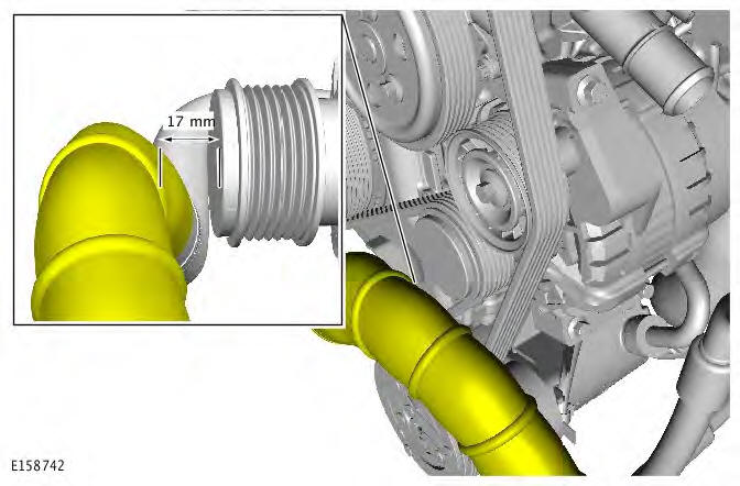
8. CAUTION: Note the alignment of the pipe during this step.
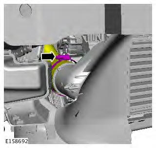
9. Torque: 5 Nm
10. Refer to: Front Bumper Cover (501-19, Removal and Installation).
11. NOTE: Repeat the above step for the other side. Refer to: Fender Splash Shield (501-02 Front End Body Panels, Removal and Installation).
Charge Air Cooler Outlet Pipe
Removal
CAUTION: Make sure that all openings are sealed. Use new blanking caps.
NOTES:
Some variation in the illustrations may occur, but the essential information is always correct.
Removal steps in this procedure may contain installation details.
1. WARNING: Do not work on or under a vehicle supported only by a jack. Always support the vehicle on safety stands. Raise and support the vehicle.
2. Refer to: Engine Cover - GTDi 2.0L Petrol (501-05 Interior Trim and Ornamentation, Removal and Installation).
3. Refer to: Front Bumper Cover (501-19, Removal and Installation).
4. Torque: 5 Nm
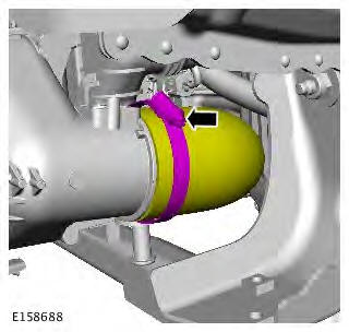
5.
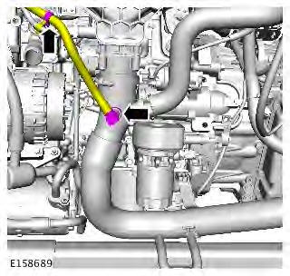
6.
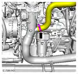
7. Torque: 5 Nm
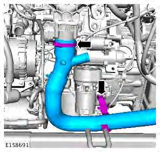
Installation
1. To install, reverse the removal procedure.

