Range Rover Evoque: Electric Booster Heater - Description and Operation
Component Location
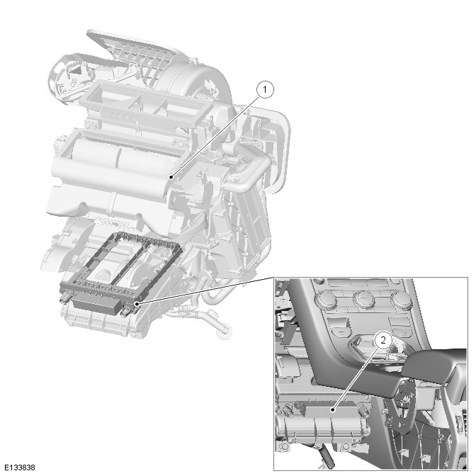
COMPONENT LOCATION

- Heater assembly
- Electric booster heater
Overview
OVERVIEW
Due to the slower warm up times associated with the diesel engine, an electric booster heater may be fitted to increase heater performance. The electric booster heater does this by heating the air leaving the heater assembly. The electric booster heater comprises ceramic coated thermistor elements and a microcontroller. A request for electric booster heater operation originates in the ATC (automatic temperature control) module. This request is transmitted to the CJB (central junction box) over the medium speed CAN (controller area network) bus. The CJB interprets this request and outputs a PWM (pulse width modulation) signal to the electric booster heater microcontroller. The duration of the pulses provided by the CJB is proportional to the amount of heating required.
The amount of heating requested by the ATC is based on:
- Ambient air temperature
- ECT (engine coolant temperature)
- Heating request.
NOTE: There is also a minimum blower motor speed required by the electric booster heater operation.
The electric booster heater is limited to 1.25 kW. If electrical load management is in force, electric booster heater performance will be reduced.
System Operation and Component Description
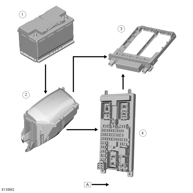
Control Diagram
NOTE: A = Hardwired;

- Battery
- BJB (battery junction box)
- PTC (positive temperature coefficient) heater
- CJB (central junction box)
System Operation
General
Operation of the electric booster heater is controlled by the ATC (automatic temperature control), which communicates with the micro-controller in the booster heater using the LIN (local interconnect network) bus. The temperature requested by the ATC module is based on:
- The ambient air temperature
- The engine coolant temperature
- The temperatures selected on the integrated control panel.
The blower must be running for the electric booster heater to operate.
If the electrical load management is in force, the electric booster heater performance is reduced. For additional information, refer to: Refer to: Electronic Engine Controls (303-14A Electronic Engine Controls - TD4 2.2L Diesel, Description and Operation).
Component Description
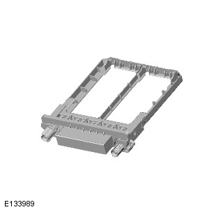
Electric Booster Heater

The electric booster heater is installed in the heater assembly, on the downstream side of the heater core. It consists of ceramic coated thermistor elements, rated at 1.25 kW, and a micro-controller. Electrical power for the booster heater is supplied by the BJB via a 100 A megafuse.

