Range Rover Evoque: Glass, Frames and Mechanisms - Component Location, System Operation and Component Description
Component Location
COMPONENT LOCATION - DOOR MECHANISMS
- Passenger door glass motor
- Passenger door module
- Rear door glass motor
- Rear door module
- Rear fuse box
- Rear door glass motor
- Rear door module
- Driver door glass motor
- Driver door module
- CJB (central junction box)
COMPONENT LOCATION - GLASS ROOF PANEL BLIND
- BJB (battery junction box)
- Battery
- CJB
- Overhead console
- Control unit/motor
Overview
OVERVIEW
Door Mechanisms
Operation of the window lift system is controlled by the CJB (central junction box) in conjunction with the driver door module and the front passenger door module. The door modules are mounted on the regulators of their respective front windows. Door modules are also mounted on both rear window regulators, and communicate with the front door modules over the LIN (local interconnect network) bus.
The window lift system features one shot up and down operation, plus an anti-trap feature for all door windows.
If the battery is disconnected, the window lift system will require calibrating on battery re-connection. To calibrate the system the following routine must be carried out.
With the ignition on:
- Fully close the door glass and release the switch.
- Re-apply the switch to close the door glass and hold for approximately 2 seconds.
- Fully open the door glass and release the switch.
- Re-apply the switch to open the door glass and hold for approximately 2 seconds.
- Repeat for all remaining windows.
Fixed Glass
The laminated windshield is bonded and sealed to the body aperture using PU (polyurethane) adhesive. Bonded to the inner surface of the windshield is the mounting boss for the interior mirror. Dependent on vehicle specification, the windshield may contain 2 heating elements between the windshield laminations.
The toughened rear screen is also bonded and sealed to the body aperture using PU adhesive. A single heating element is printed on the inner surface of the rear screen.
The rear quarter window glass is bonded and sealed to the body aperture using PU adhesive.
Glass Roof Panel Blind
The glass roof panel blind is electrically operated through a 2 way rocker switch located in the overhead console. An electric motor, attached to the front of the frame of the glass roof, drives the blind. The blind is operated by 2 cables, which are driven by the motor.
Operation of the glass roof panel blind is controlled by the blind control unit, which is integral with the motor. The control unit receives inputs from the CJB and the switch to control the blind operation accordingly.
System Operation and Component Description
Control Diagram
Door Glass Opening Mechanisms
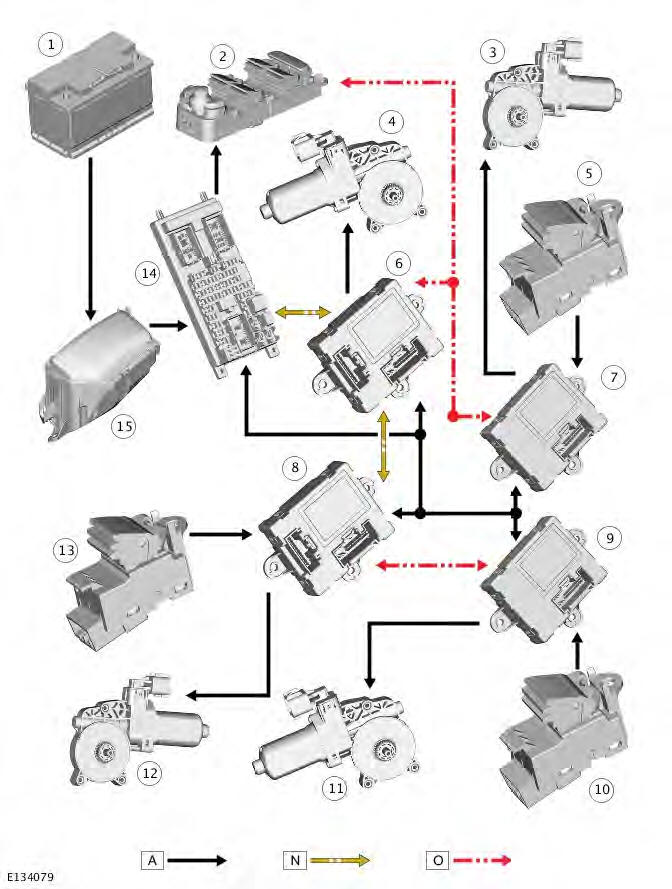
A = Hardwired; N = Medium speed bus; O = bus.
- Battery
- Driver door switch pack
- Rear door glass motor
- Driver door glass motor
- Rear door window lift switch
- Driver door module
- Rear door module
- Passenger door module
- Rear door module
- Rear door window lift switch
- Rear door glass motor
- Passenger door glass motor
- Passenger door window lift switch
- CJB (central junction box)
- BJB (battery junction box)
Glass Roof Panel Blind
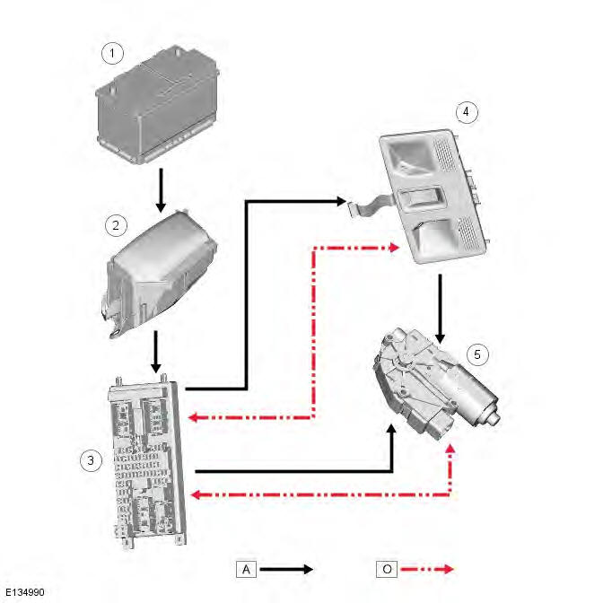
A = Hardwired; O = bus.
- Battery
- BJB
- CJB
- Overhead console
- Control unit/motor
System Operation
PRINCIPLES OF OPERATION
Door Glass Opening Mechanisms
The CJB provides a power supply to the driver door switch pack when the vehicle is in power mode 6 (ignition on). Switch requests made using the driver door switch pack are then delivered to the driver door module over the LIN bus.
The driver door module interprets the request made using the switch pack and responds as follows:
- If the request is for driver's side rear window operation, a request is transmitted over the LIN bus to the driver side rear door module.
- If the request is for front passenger window operation, a request is transmitted over the medium speed CAN bus to the passenger door module.
- If the request is for passenger side rear window operation, a request is transmitted over the medium speed CAN bus to the passenger door module. This request is then forwarded over the LIN bus to the passenger side rear door module.
Door Glass Opening and Closing
Each door module provides 2 signal feeds to its window lift switch. When a switch request is made, a ground path is created on one of the lines via the door module. From this the door module can determine which direction of travel has been requested.
The door modules power the door glass motors on receipt of a switch request or a request for Global Closing (see below).
The door modules provide feed and return paths to their respective motor, which can switch depending on the direction of travel requested.
The door glass motor assemblies also contain a Hall effect sensor. The Hall effect sensor allows the door module to determine the position of the door glass and if a motor stall condition has taken place.
Global Closing
The CJB provides a constant battery feed to the 4 door modules. This feed is used to operate the 'Global Closing' feature.
Global Closing allows all 4 windows to be closed using the Radio Frequency (RF) handset.
NOTE: The glass roof panel blind is not part of the Global Closing feature.
The Global Closing feature is activated by pressing and holding the 'lock' button on the RF handset for 3 seconds. The request for Global Closing is provided to the CJB by the RF receiver. The CJB then transmits this request to the driver and passenger door modules over the medium speed CAN bus.
Initialization
When the vehicle is delivered from the factory the window lift system will operate slowly until it has been initialized. The initialization process should be carried out using the PDI (pre-delivery inspection) feature contained within the Land Rover approved diagnostic system. For more information, refer to the PDI manual.
Similarly, if a door module is replaced, the new module will require initialization before handover to the customer. The initialization process for a new module is carried out using the 'New Module' feature contained within the Land Rover approved diagnostic system.
Glass Roof Panel Blind
The glass roof panel blind will only operate when the vehicle is in power mode 6 (ignition on). Power is supplied to the blind control unit/motor by the CJB, which supplies both a permanent battery and ignition power supply.
Switch Inputs
The switch for the glass roof panel blind is mounted in the overhead console and is provided with 2 signal feeds by the control unit. When the switch is in the rest (central) position, both connections from the control unit are open circuit.
When the switch is pressed to open the blind, the signal feed from pin 4 of the control unit electrical connector is provided a ground path through the switch contacts. When the switch is pressed to close the blind, the switch grounds the signal feed from pin 8 of the control unit electrical connector.
Anti-Trap
The glass roof panel blind motor is calibrated to detect a blockage that will prevent the blind from closing. The force required to close the blind will not exceed 100 N. If a blockage is detected, the control unit will power the motor in the opposite direction to reverse the position of the blind by 200 mm.
Calibration
If the battery is disconnected, or the power supply is interrupted while the glass roof panel blind is moving, it will need to be re-calibrated.
Once the battery is reconnected, or the power supply is restored, recalibrate the blind as follows:
- Start the engine and leave it running during the calibration procedure.
Ensure the blind is in the fully closed position; press the close side of the switch to achieve this.
- Press and hold the close side of the switch again and wait for the cables to double click (it should take about 30 seconds), then release the switch.
- Within 3 seconds, press and hold the close side of the switch again.
- The blind will automatically travel to the open position (approximately 300 mm) and then the closed position. Do not release the switch until the blind has returned to the fully closed position. If the switch is released by mistake, repeat the complete procedure.
Component Description
DOOR MODULES
In addition to controlling the window lift system, the front door modules also control:
- Door locking.
Refer to: Handles, Locks, Latches and Entry Systems (501-14 Handles, Locks, Latches and Entry Systems, Description and Operation).
- Door mirror adjustment and heating.
Refer to: Rear View Mirrors (501-09 Rear View Mirrors, Description and Operation) / Control Components (412-01 Climate Control, Description and Operation).
- Door mirror lamps.
Refer to: Interior Lighting (417-02 Interior Lighting, Description and Operation).
The rear door modules control window lift and door locking only.
The door modules are color coded for position on the vehicle. The driver door module and both rear door modules are black.
The passenger door module is gray. The electrical wiring harness connectors are also color coded to match the door modules.
NOTE: Both rear door modules are identical.
If a front door module develops a fault, a DTC (diagnostic trouble code) is stored in its memory. The DTC can be read using the Land Rover approved diagnostic system. If either of the rear door modules develops a fault, the DTC is stored in the respective front door module.
Refer to: Glass, Frames and Mechanisms (501-11 Glass, Frames and Mechanisms, Description and Operation).
GLASS ROOF PANEL BLIND CONTROL UNIT/MOTOR
- Motor
- Control unit
The combined control unit and motor assembly is mounted behind the headlining, to the front of the glass roof panel blind.
The control unit uses inputs from the CJB and the blind switch to control operation of the motor.
The end of the motor armature is formed as a worm drive, which drives a gear attached to the end of the motor assembly.
The gear engages with helixed cables in the blind frame to form a rack and pinion drive.
The control unit incorporates a Hall effect sensor which is used to count the revolutions made by the motor armature. By counting the revolutions the control unit can accurately determine when the blind has reached its fully open or closed position, by comparing the armature rotation value against values stored in its memory. The values are stored in the control unit's memory during the calibration procedure.
GLASS ROOF PANEL BLIND
- Blind
- Blind guide
- Control unit/motor
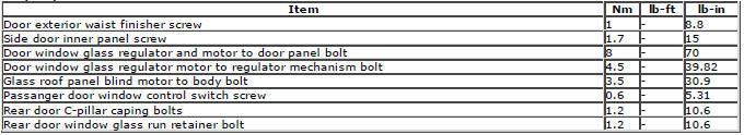
Torque Specifications
READ NEXT:
 Front/Rear Door Window Glass
Front Door Window Glass
Special Tool(s)
501-114
Release Lever, Door Glass
Removal
NOTE: Removal steps in this procedure may contain installation details.
1. Torque: 1 Nm
2. Special Tool(s): 501-114
Rear Quarter Window Glass 3-Door
Removal
1. Refer to: Rear Quarter Panel Moulding (501-08 Exterior Trim and
Ornamentation, Removal and Installation).
2. Refer to: B-Pillar Upper Trim Panel - 3-Door (501-05 Interior Trim and
Ornamenta
Liftgate Window Glass
Removal
1. Refer to: Rear Spoiler (501-08 Exterior Trim and Ornamentation,
Removal and Installation).
2.
3.
4. CAUTION: The step must be carried out on both
sides.
5. CAUTIONS:
Protect the surroun
SEE MORE:
Important information
The information contained in this handbook covers all vehicle derivatives and
optional equipment,
some of which may not be fitted to your vehicle. Due to printing cycles, this
handbook may include
descriptions of options before they become generally available.
The vehicle options, hardware an
Symbols used in this handbook
Safety warnings indicate either a procedure which must be followed
precisely, or
information that should be considered with great care, in order to avoid the
possibility
of personal injury.
Cautions indicate either a procedure which must be followed precisely, or
information that
should
